Download
1 / 31
310 likes | 370 Views
Dive into self-inductance, mutual inductance, and energy storage in magnetic fields. Explore LR and LC circuits, electromagnetic oscillations, and AC circuit resonance. Learn about LRC circuits and impedance matching in three-phase AC circuits.

E N D
Chapter 32: Inductance, Electromagnetic Oscillations, and AC Circuits
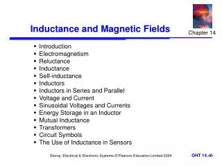
Outline of Chapter • Self-Inductance • Mutual Inductance • Energy Stored in a Magnetic Field • LR Circuits • LC Circuits and Electromagnetic Oscillations • LC Circuits with Resistance (LRC Circuits) • AC Circuits with AC Source • LRC Series AC Circuit • Resonance in AC Circuits • Impedance Matching • Three-Phase AC
Inductance Self-Inductance • A time-varying current in a circuit produces an induced emf opposing the emf that initially set up the time varying current. • Basis of the electrical circuit element called an inductor • Energy is stored in the magnetic field of an inductor. • There is an energy density associated with the magnetic field. Mutual Inductance • An emf is induced in a coil as a result of a changing magnetic flux produced by a second coil. • Circuits may contain inductors as well as resistors and capacitors.
Some Terminology • Use the terms emfand currentwhen they are caused by batteries or other sources. • Use the terms induced emfand induced currentwhen they are caused by changing magnetic fields. • In problems in electromagnetism, it is important to distinguish between the two situations.
Self-Inductance • Consider the circuit in the figure. • When the switch is closed, the current does not immediately reach its maximum value. • Faraday’s Law of Inductioncan be used to describe this. • As the current increases with time, the magnetic flux through the circuit loopdue to this current also increases with time. This increasing flux creates an induced emf in the circuit.
The direction of the induced emfis such that it would cause an induced current in the loop which would establish a magnetic field opposing the changein the original magnetic field. Lenz’s Law at work! • The direction of the induced emfis opposite the directionof the emf of the battery. • This results in a gradual increase in the current to its final equilibrium value. This effect is called self-inductance. • Because the changing flux through the circuit & the resultant induced emf arise from the circuit itself. • The emfεL is called a self-induced emf.
Self-Inductance • An induced emf is always proportional to the time rate of change of the current. • By Faraday’s Law, the induced emf is proportional to the flux, which is proportional to the field and the field is proportional to the current. • So, we can write: • L is a constant of proportionality called the (self) inductance of the coil. • It depends on the geometry of the coil and other physical characteristics.
Self-Inductance • An important aspect of Faraday’s Law is: • A changing current in a coil will induce an emf in itself: Note: This is the same as L. Sorry! Lis called the self-inductance:
Joseph Henry 1797 – 1878 • American physicist. • First director of the Smithsonian. • First president of the Academy of Natural Science. • Improved design of Electromagnets. • Constructed one of the first motors. • Discovered self-inductance. • Didn’t publish his results. The SI unit of inductance, the Henry is named in his honor.
Inductance Units • The SI unit of inductance is the Henry (H) • Named for Joseph Henry
Inductance of a Coil • A closely spaced coil of N turns carrying current I has an inductance of • Physically, the inductance is a measure of the opposition to a change in current.
Inductance of a Solenoid • Assume a uniformly wound solenoid with N turns & length ℓ.Assume that ℓ is much greater than the solenoid radius. • The flux through each turn of area A is • The inductance is • This shows that L depends on the object’s geometry.
Example Solenoid Inductance. Calculate the value of L for N = 100, l = 5.0 cm, A = 0.30 cm2, and the solenoid is air filled.
Example Solenoid Inductance. Calculate the value of L for N = 100, l = 5.0 cm, A = 0.30 cm2, and the solenoid is air filled. Answer: L = 7.5 μH
Conceptual Example Direction of emf in inductor. Current passes through a coil from left to right as shown. (a) If the current is increasing with time, in which direction is the induced emf? (b) If the current is decreasing in time, what then is the direction of the induced emf?
Example: Self- Inductance of a Coaxial Cable • Calculate L for a length ℓfor the coaxial cable in the figure. • The total flux is • Therefore, L is
LR Circuits A circuit consisting of an inductor and a resistor will begin with most of the voltage drop across the inductor, as the current is changing rapidly. With time, the current will increase less and less, until all the voltage is across the resistor.
Example : An LR circuit. At t = 0, a 12.0-V battery is connected in series with a 220-mH inductor and a total of 30-Ω resistance, as shown. (a) What is the current at t = 0? (b) What is the time constant? (c) What is the maximum current? (d) How long will it take the current to reach half its maximum possible value? (e) At this instant, at what rate is energy being delivered by the battery, and (f) at what rate is energy being stored in the inductor’s magnetic field?
. . The sum of potential differences around the loop gives Integrating gives the current as a function of time: The time constant of an LR circuit is .
. If the circuit is then shorted across the battery, the current will gradually decay away:
Mutual Inductance • Mutual Inductance: A changing current in one • coil will induce a current in a second coil: & vice versa. Note that the constant M,known as the mutual inductance, is has the form:
A transformer is an example of a practical application of mutual inductance.
Solenoid and coil. A long thin solenoid of length l and cross-sectional area A contains N1 closely packed turns of wire. Wrapped around it is an insulated coil of N2 turns. Assume all the flux from coil 1 (the solenoid) passes through coil 2, and calculate the mutual inductance.
Conceptual Example: Reversing the coils. How would the previous Example change if the coil with turns was inside the solenoid rather than outside the solenoid?
Energy Stored in a Magnetic Field Just as we saw that energy can be stored in an electric field, energy can be stored in a magnetic field as well, in an inductor, for example. Analysis shows that the energy density of the field is given by
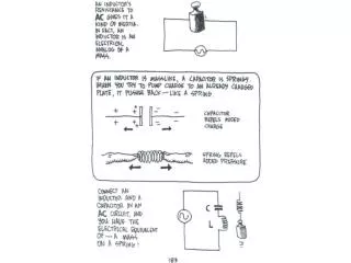
LC Circuits & Electromagnetic Oscillations An LC circuit is a charged capacitor shorted through an inductor.
. Summing the potential drops around the circuit gives a differential equation for Q: This is the equation for simple harmonic motion, and has solutions .
Substituting shows that the equation can only be true for all times if the frequency is given by The current is sinusoidal as well:
The charge and current are both sinusoidal, but with different phases.
The total energy in the circuit is constant; it oscillates between the capacitor and the inductor:
Example: LC circuit. A 1200-pF capacitor is fully charged by a 500-V dc power supply. It is disconnected from the power supply and is connected, at t = 0, to a 75-mH inductor. Determine: (a) the initial charge on the capacitor; (b) the maximum current; (c) the frequency f and period T of oscillation; and (d) the total energy oscillating in the system.