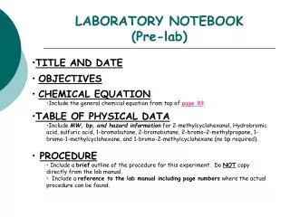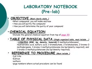

EECT112 LAB NOTEBOOK
E N D
Presentation Transcript
EECT112LAB NOTEBOOK Fall 2014 Instructor: Louis Toth Partner: Josiah Abel By Dakota Johnson
Table of Content Lab Number Slide Number • Lab 1( And/Or Gates) 3-5 • Lab 2(NandAlternative) 6-10 • Lab 3(Car Alarm) 11-13 • Lab 4(Binary Counter) 14-16 • Lab 5(LED Flasher) 17-21 • Lab 6(Temp Sensor/Heater) 22-26
Lab 1And/Or Gates • Equipment: • Breadboard • Brand: NI ELVIS II+ • SN: 14C6E29 • Digital Multimeter • Brand: GWINSTEK • GDM: 3245 • SN: CL860334 • -AND Gate • Chip: 74LS08D • OR Gate • Chip: 74LS32D • -Miscellaneous Wire Objective: To show the functions of AND and OR gates. Background: An And Gate sends an output when all inputs are sending a signal. An Or Gate sends an output when just one input sends a signal.
Lab 1And/Or Gates Schematics: Multisim Schematics for the chips Resistors Or Gate And Gate Individual gates Power to the chip Gate inputs Gate output Ground for the chip LED Lights Switches
Lab 1And/Or Gates Lab Work: Resistors And Gate LED Lights Switches The voltage of the circuit was taken using an oscilloscope. The voltage when the LEDs were on was 3.22 V and when they were off it was .16 V. Or Gate
Lab 2Nand Alternative • Equipment: • Breadboard • Brand: NI ELVIS II+ • SN: 1677D1E • Digital Multimeter • Brand: GWINSTEK • GDM: 8245 • SN: CL860332 • -AND Gate • Chip: 74LS08D • OR Gate • Chip: 74LS32D • -NOT Gate • Chip: 74LS04D • -NAND Gate • Chip: 74LS00D • -Miscellaneous Wire Objective: To show how a logic circuit can be reduced to a single kind of gate. Background: Not gates work by inverting whatever signal is going into it. Nand gates behave like the inverse of an And gate so a Nand gate will send an output when one or both of the signals have a logic state of 0 and will not send a signal when both of the signals are a logic state of 1. Nand gates also have a universal property. This means that you can build a circuit using only Nand gates. NAND
Lab 2Nand Alternative Schematics: Multisim Nand Gates Resistors Switches LED Lights Or Gates And Gate Not Gates
Lab 2Nand Alternative Schematics: Schematics for the chips Individual Nand gate Power to the chip Individual Not gate Gate input Gate inputs Power to the chip Gate output Power to the chip Individual Or gate Gate output Gate inputs Ground for the chip Ground for the chip Gate output Ground for the chip
Lab 2Nand Alternative Lab Work: Nand Gates LED Lights Not Gates Switches Or Gates And Gate Resistors
Lab 2Nand Alternative Lab Work: Using an oscilloscope the voltage was taken when the LEDs were on (left picture), when the LEDs were off (center picture), and when the prongs were placed directly on the wires (right picture).
Lab 3(Mid Term)Car Alarm • Equipment: • Breadboard • Brand: NI ELVIS II+ • SN: 14C6E29 • -AND Gate • Chip: 74LS08D • OR Gate • Chip: 74LS32D • -Miscellaneous Wire Objective: To build a functioning logic circuit given the inputs and desired outputs. Background: The diagram below was given. The desired outputs were when the door was open and the ignition was on, when the door was open and the lights were on, and when the ignition was off and the lights were on.
Lab 3(Mid Term)Car Alarm Schematics: Multisim Truth Table Ignition Input Light Input LED representing car alarm Door Input And Gate Or Gate Equation found from truth table* Switches Resistors X = (ID)+L * There was a mistake made when finding this equation. Because of this the circuit built gives off false positives.
Lab 3(Mid Term)Car Alarm Lab Work: LED representing car alarm And Gate Door Input Switches Ignition Input Resistors Light Input Or Gate
Lab 4Binary Counter • Equipment • Breadboard • Brand: NI ELVIS II+ • SN: 1677D3B • -BCD to 7 Segment Decoder • Chip: 74LS48D • 4 Bit Ripple Counter • Chip: 74LS93D • Tektronix TDS 220 Two Channel Digital Real-Time Oscilloscope • SN:B068379 • -Man 74-7 Segment display • -Miscellaneous Wire Objective: To have a 7 segment display count from 0 to F in hexadecimal. Background: A clock when used with a flip flop latch can be used to store information and count.
Lab 4Binary Counter Schematics: Multisim 7 Segment Display 4-Bit Ripple Counter BCD to 7 Segment Decoder Clock
Lab 4Binary Counter Lab Work: 4-Bit Ripple Counter 7 Segment Display Clock An oscilloscope was attached to the circuit so that the waves of the clock could be observed. BCD to 7 Segment Decoder
Lab 5LED Flasher(Basic Stamp 1) Equipment -LED Light -220 ohm resistor -10k ohm resistor -Basic Stamp -Basic Stamp Program -Miscellaneous Wire Objective: To program a chip to flash an LED light Background: The basic stamp program allows you to program a chip to do different functions.
Lab 5LED Flasher(Basic Stamp 1) Schematics: Program Defining Variables and Constants Defining Inputs and Outputs Initial Conditions Comments about what the program is doing Main Program Sub-routine
Lab 5LED Flasher(Basic Stamp 1) Schematics: Hardware LED Light Switch Resistors
Lab 5LED Flasher(Basic Stamp 1) Lab Work: Switch LED Light Programmable Chip 220 ohm resistor 10k ohm resistor
Lab 5LED Flasher(Basic Stamp 1) Lab Work:
Lab 6Temp Sensor/Heater (Basic Stamp 2) Equipment -LED Light -220 ohm resistor -10k ohm resistor -10K ohm Multi-turn Potentiometer -1uF Capacitor -Basic Stamp -Basic Stamp Program -Miscellaneous Wire Objective: To show how analog data can be used in a digital circuit. Background: Digital data comes in two states on or off. Analog data can come in varying degrees of states. There are multiple was to get analog data into a digital circuit in this experiment we will be using a resistor/capacitor network for the analog data and the input will be the time it take for the capacitor to discharge.
Lab 6Temp Sensor/Heater (Basic Stamp 2) Schematics: Program Defining Variables and Constants Defining Inputs and Outputs Main Program Comments about what the program is doing Sub-routines
Lab 6Temp Sensor/Heater (Basic Stamp 2) Schematics: Hardware LED Light Switch Capacitor Resistors Potentiometer
Lab 6Temp Sensor/Heater (Basic Stamp 2) Lab Work: Capacitor Switch Programmable Chip 220 ohm resistor Potentiometer 10k ohm resistor LED Light
Lab 6Temp Sensor/Heater (Basic Stamp 2) Lab Work: The debug screen saying that the heater energized at 100. The debug screen saying that the heater de-energized at 121.