Download
1 / 40
400 likes | 424 Views
Explore advanced topics like Nested State Diagrams, Signal Generalization, and Concurrency in Object-Oriented Modeling and Design. Learn how to structure complex systems effectively using interaction models.

E N D
Subject Name: Object oriented Modeling and Design Subject Code: 10MCA51 Prepared By: Supriya.N.S Department: MCA Date:26/08/14
UNIT 3- Advanced State Modeling, Interaction Modeling and Advanced Interaction Modeling 3.1 Nested State Diagrams 3.2 Nested States 3.3 Signal Generalization 3.4 Concurrency 3.5 A Sample State Model 3.6 Use Case Models 3.7 Sequence Models 3.8 Activity Models 3.9 Use Case Relationships 3.10 Procedural Sequence Models 3.11 Special Constructs for Activity Models
3.1 Nested State Diagrams 3.1.1 Problems with Flat state diagram The state diagrams are sufficient for describing basic systems but need additional things to handle large problems. E.g.: Consider an object with ‘Z’ independent Boolean attributes that affect control. Representing such an object with a single flat state diagram would require 2z states. For partitioning the state into n independent state diagrams, only 2z states are required.
3.1.2Expanding States:One way to organize a model is by having a high-level diagram with sub diagrams expanding certain states Figure-3.1: Vending Machine State Diagram
3.2 Nested States Second alternative for structuring states is using nested states. UML2 avoids using generalization in conjunction with states. Local state can be replaced with “nested states”. Figure 3.2: Nested States for Phone line
3.3 Signal Generalization Signals can be organized into a generalization hierarchy with inheritance of signal attributes. It permits different levels of abstraction to be used in a model FIGURE 3. 3: GENERALIZATION OF SIGNALS
3.4 Concurrency The State Model Supports different types of concurrency. 3.4.1Aggregation Concurrency 3.4.2 Concurrency within an Object 3.4.3 Synchronization of Concurrent Activities
3.4.1Aggregation Concurrency The aggregate state corresponds to the combined states of all the parts. Aggregation is the “and-relationship”. Transitions for one object can depend on another object being in a given state. 3.4.2Concurrency within an Object You can partition some objects into subsets of attributes or links, each of which has its own sub diagram. The state of the object comprises one state from each sub diagram. 3.4.3Synchronization of Concurrent Activities The object does not synchronize the internal steps of the activities but must complete both activities before it can progress to its next state.
Figure 3.5: Bridge game with concurrent states Figure 3.6: Synchronization of control
3.5 A SAMPLE STATE MODEL Figure 3.7: Thermostat User Interface
3.6 Interaction Modeling 3.6.1 Use Case Models 3.6.2 Sequence Models 3.6.3 Activity Models
3.6 Use Case Models 3.6.1 What is Use Case Models? The interaction model describes how the objects interact. Behavior of the system is needed to be described by State model and Interaction model. Use cases are helpful for capturing informal requirements. Sequence diagrams are good for showing the behavior sequences seen by users of a system. Activity diagrams can show data flows as well as control flows. Use case Models contains: Actors: An actor is a direct external user of a system Use cases: A use case is a coherent piece of functionality that a system can provide by interacting with actors
3.6.2 Guidelines for Use case Models • First determine the system • Ensure that actors are focused • Each use case must provide value to users. • Relate use cases and actors • Remember that use cases are informal • Use cases can be structured
3.7 Sequence Models • The sequence model elaborates the themes of use cases. • Two kinds of sequence models: • scenarios • more structured format called sequence diagrams • 3.7.1 Scenarios • A scenario is a sequence of events that occurs during one particular execution of a system, such as for a use case. A scenario can be displayed as a list of text statement.
Scenario for a session with an online stock broker • Marie logs in • System establishes secure communications • System displays portfolio information • Marie enters a buy order for 100 shares of GE at the market price • System verifies sufficient funds for purchase • System displays confirmation screen with estimated cost • Marie confirms purchase • System places order on securities exchange • System displays transaction tracking number • Marie logs out • System establishes insecure communications • System displays good-bye screen • System exchange reports results of trade
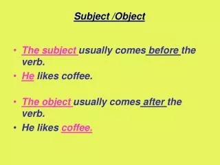
3.7.2 Sequence Diagrams A sequence diagram shows the participants in an interaction and the sequence of messages among them. Each actor as well as the system is represented by a vertical line called a lifeline and each message by a horizontal arrow from the sender to the receiver. Each use case requires one or more sequence diagrams to describe its behavior. Prepare one sequence diagram for each major flow of control Draw a separate sequence diagram for each task. Prepare a sequence diagram for each exception condition within the use case Try to elaborate all the use cases and cover the basic kinds of behavior with sequence diagrams
3.7.3 Guidelines for Sequence Models • Prepare at least one scenario per use case • Abstract the scenarios into sequence diagrams • Divide complex interactions • Prepare a sequence diagram for each error condition
3.8 Activity Models An activity diagram shows the sequence of steps that make up a complex process, but focuses on operations rather than on objects. Activity diagrams are most useful during the early stages of designing algorithms and workflows. Activities The steps of an activity diagram are operations, specifically activities from the state model. Executable Activity Diagrams An activity token can be placed on an activity symbol to indicate that it is executing. Multiple tokens can arise through concurrency.
3.8.1 Activities The steps of an activity diagram are operations, specifically activities from the state model. Figure 3.14: Activity diagram for execute order.
3.8.2 Executable Activity Diagrams • An activity token can be placed on an activity symbol to indicate that it is executing. Multiple tokens can arise through concurrency. • 3.8.3 Guidelines for Activity Models • Don’t misuse activity diagrams. • Activity diagrams are intended to elaborate use case should not be used as an excuse to develop software via flowcharts. • Level diagrams • Consider executable activity diagrams
3.9 Use Case Relationships • Use cases can be structured for large applications. Complex use cases can be built from smaller pieces with the following relationships: • 3.9.1 Include • 3.9.2 Extend • 3.9.3 Generalization
3.9.1 Include Relationship • The include relationship incorporates one use case within the behavior sequence of another use case • The UML notation for an include relationship is a dashed arrow from the source use case to the target (included) use case • The keyword <<include>> annotates the arrow • A use case can also be inserted within a textual description with the notation include use-case-name. • Factoring a use case into pieces is appropriate when the pieces represent significant behavior units.
3.9.2 Extend Relationship • The extend relationship adds incremental behavior to a use case • It represents the frequent situation in which some initial capability is defined, and later features are added modularly • Example • A stock brokerage system might have the base use case trade stocks, which permits a customer to purchase stocks for cash on hand in the account. • The additional behavior is inserted at the point where the purchase cost is checked against the account balance. • The UML notation for extend relationship is a dashed arrow from the extension use case to the base use case
3.9.3 Generalization Generalization can show specific variations on a general use case, analogous to generalization among classes The UML indicates generalization by an arrow with its tail on the child use case and a triangular arrowhead on the parent use case, the same notation that is used for classes 3.17 Use case extension
3.9.4 Combinations of Use case Relationships A single diagram may combine several kinds of use case relationships 3.18 Use case Relationship
3.9.5 Guidelines for Use case Relationships • Use case generalization • Use case inclusion • Use case extension • Include relationship vs. extend relationship
3.10 Procedural Sequence Models The UML has elaborations for sequence diagrams to show procedure calls. 3.10.1 Sequence Diagrams with Passive Objects Most objects are passive and do not have their own threads of control. Activation shows the time period during which a call of a method is being processed, including the time when the called method has invoked another operation. 3.19 Sequence Diagrams with Passive Objects
3.10.2 Sequence Diagrams with Transient Objects ObjectA is an active object that initiates an operation. The notation for a call is an arrow from the calling activation created by the call. Activation, therefore, has a call arrow coming into its top and a return arrow leaving its bottom. If an object does not exist at the beginning of a sequence diagram, then it must be created during the sequence diagram. Figure 3.20 Sequence Diagrams with Transient Objects
3.11 Special Constructs for Activity Models 3.11.1Sending & Receiving Signals: The UML shows the sending of a signal as a convex pentagon & Receiving of a signal as a concave signal. Figure 3.21 Activity diagram with signals
3.11.2 Swimlanes • In a business model, it is often useful to know which human • organization is responsible for an activity. • Example: Sales, finance, marketing, and purchasing • It is sufficient to partition the activities among organizations. • Lines across swimlane boundaries indicate interactions among different organizations. Figure: 3.22Activity diagram with swimlanes.
3.11.3 Object Flows It is helpful to see the relationships between an operation and the objects that are its argument values or results. An input or output arrow implies a control flow. Frequently the same object goes through several states during the execution of any activity diagram.UML shows an object value in a particular state by placing the state name in square brackets following the object name . Figure 3.23 Activity diagram with object flows.