Download
1 / 8
80 likes | 241 Views
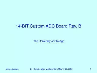
14-BIT Custom ADC Board. Mircea Bogdan The University of Chicago JParc-K Collaboration Meeting April 27-29, 2007, Osaka, Japan. 14-Bit, 125MHz ADC Board – Block Diagram. Each ADC channel - one AD9254 chip: 14 bits/125MHz; 7-Pole Filter/Shaper Included on Board;

E N D
14-BIT Custom ADC Board Mircea BogdanThe University of Chicago JParc-K Collaboration Meeting April 27-29, 2007, Osaka, Japan
14-Bit, 125MHz ADC Board – Block Diagram • Each ADC channel - one AD9254 chip: 14 bits/125MHz; • 7-Pole Filter/Shaper Included on Board; • One STRATIX II FPGA EP2S60F1020 for 16 ADC channels: • Trigger rate: 10kHz, 32 samples/trigger (256ns); • Input Pipeline: ~25us depth (3,200 samples); • Two VME readout buffers - max 128 triggers, (10 ms); • Optical Link with: TLK2501, V23829-N305-B57 (can be stuffed if needed).
Schematic – Top Level Front Panel LVDS Inputs*: • 8-Bit Parallel: • Sys clock, triggers from TS; Front Panel LVDS Outputs*: • 16-Bit Parallel, 12-Bit Serialized: • Board Energy Info to TS; Readout: • VME32/64 with CBLT; • GLINK/SLINK if needed. Actual Board schematic – DA/Mentor Graphics (*) Comments regarding the number of I/O Bits are welcome.
Schematic – Shaper/ADC Channel Adjustable Gain Actual Board schematic – DA/Mentor Graphics
Schematic – FPGA Block Actual Board schematic – DA/Mentor Graphics
Altera Project – Block Diagram Actual Basic FPGA Design – Altera Quartus Design is sufficient for beam test only: can record, store, and read out 3,200 samples/25us. To Do: - Trigger/Memory/Control block (BTE calculator, Pipeline, Data Packer, Control, etc.); - G-Link Interface – if needed.
Conclusions • Good simulation results on PreAmp/Shaper schematic and FPGA design; • Have to proceed now with the prototype;