Chapter 36: Image Formation
660 likes | 912 Views
Chapter 36: Image Formation. Reading assignment: Chapter 36 Homework 36.1 ( Fri day , May 3, only the first seven problems, plane and concave mirror): OQ2, OQ6, 1, 2, 8, 9, 10 ); rest of the problems (convex mirror) is extra credit: 11, 13, 18, 22, 25

Chapter 36: Image Formation
E N D
Presentation Transcript
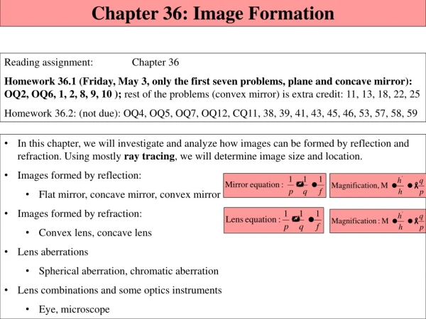
Chapter 36: Image Formation Reading assignment: Chapter 36 Homework 36.1(Friday, May 3, only the first seven problems, plane and concave mirror): OQ2, OQ6, 1, 2, 8, 9, 10 ); rest of the problems (convex mirror) is extra credit: 11, 13, 18, 22, 25 Homework 36.2:(not due): OQ4, OQ5, OQ7, OQ12, CQ11, 38, 39, 41, 43, 45, 46, 53, 57, 58, 59 • In this chapter, we will investigate and analyze how images can be formed by reflection and refraction. Using mostly ray tracing, we will determine image size and location. • Images formed by reflection: • Flat mirror, concave mirror, convex mirror • Images formed by refraction: • Convex lens, concave lens • Lens aberrations • Spherical aberration, chromatic aberration • Lens combinations and some optics instruments • Eye, microscope
Summer Session Registration (Mar 18 – May 31) Please spread the word!
Announcements • Final exam is scheduled for • Friday, May 10, 9:00 am – 12:00 pm, Olin 101 (class room). • Early date: Tuesday, May 7, 9:00 am – 12:00 pm, Olin 101 (class room). • Final exam will be comprehensive: • Chapters 23 – 29, partial 34 (EM waves, c, E, B perpendicular), 35, (partial) 36, not 37 & 38 (diffraction) • Review on Thursday, May 9, 5:00 pm – 7:00 pm, Olin 101 (class room) • I’ll send out equation sheet • Webpage will be updated (all ppt slides, all scores, etc) • Thanks for being a wonderful class!! • Best of luck to all of you!!
Summary of Geometric Optics Rules Object distances, p, are typically positive (except e.g., cases of multiple lenses or mirrors with an image on the far side of a lens, or a virtual object behind mirror). Image distances, q, are positive for real images and negative for virtual images. Real images form on the same side of the object for mirrors and on the opposite side for refracting surfaces (lenses). Virtual images form on the opposite side of the object for mirrors and on the same side for refracting surfaces. When an object faces a convex mirror or concave refracting surface the radius of curvature, R, is negative. When an object faces a concave mirror or convex refracting surface the radius of curvature is positive.
Images • We will continue to use the ray approximation of light; light travels in straight line paths called light rays. • When we see an object, according to the ray model, light reaches our eyes from each point of an object. • Light rays leave each point of an object in all directions, only a small bundle of these can enter an observers eye, who will then interpret these as an image. • Your eyes tell you where/how big an object/image is. • Mirrors and lenses can ‘fool’ your eyes; that is, create images that are bigger or smaller than the original object; images that are upright or inverted as compared to the original object; and images that are in different places than the original object.
Case 1: Flat mirror Images formed by flat mirror P P’ p q Image Object Mirror • Place a point light source P(object O) in front of a mirror. • If you look in the mirror, you will see the object as if it were at the point P’, behind the mirror. • As far as you can tell, there is a “mirror image” behind the mirror. • For an extended object, you get an extended image. • The distances of the objectfrom the mirror and the imagefrom the mirror are equal. • Flat mirrors are the onlyperfect image system(no distortion).
Image Characteristics and Definitions h h’ p q Image Object Mirror • The front of a mirror or lens is the side the light goes in. • Object distance, p,is how far the object is in front of the mirror. • Image distance, q,is how far the image is in front* of the mirror (*behind for lenses). • Real image if q > 0,virtual image if q < 0 (more on that in a bit). • Magnification, M,is how large the image is compared to the object. • Upright if positive • Invertedif negative
Real and virtual image Virtual image Light rays don’t pass through the virtual image. Rays only seem to come from the virtual image. Real image (more on that later) Light rays actually pass through the real image. A real image can be capturedon a piece of paper or film placed at the image location. A flat mirror forms a virtual, upright image with magnification 1 • Both, real and virtual images can be seen by the eye.
Case 1: Flat mirror White board example How tall must a full-length mirror be? A 1.80 m tall man stands in front of a vertical, plane mirror. What is the minimum height of the mirror and how high must its lower edge be above the floor for him be able to see his whole body? Assume his eyes are 10 cm below the top of his head. Does moving toward or away from the mirror change this? q 1.70 m q’
Case 2: Spherical mirrors Spherical Mirrors Concave mirrors • Curved mirrors for imaging are typically spherical mirrors – sections of a sphere. • Spherical mirrors will have a radius R and a center point C. • We will assume that incident rays on the mirror are small: . • (These are called paraxial rays. If q is large, we get blurry images – spherical aberration, more later) • Principal axis:an imaginary line passing through the center of the mirror. • Vertex: The point where the principal axis meets the mirror.
Case 2: Spherical mirrors Spherical Mirrors Concave mirror, focal length • Incoming parallel rays are reflected and focused at the focal point, F. • f is called the focal length of the mirror (distance from F to mirror). R V R • For a spherical mirror:
Spherical Mirrors Concave mirrors Case 2.1: Concave mirror, object outside f, outside C F Ray tracing and creating an image (We get an image were the rays converge. Typically only two rays are needed, use third ray to check) • Any ray coming in parallel goes through the focus • Any ray through the focal point, F, comes out parallel • Any ray through the center, C, comes straight back • Let’s use these rules to find the image for an object outside the focal point: Object h C h’ Image p q
Spherical Mirrors Case 2.1: Concave mirror, object outside f, outside C • Any ray coming in parallel goes through the focus • Any ray through the focal point, F, comes out parallel • Any ray through the center, C, comes straight back Ray tracing and creating an image When the object is out further than the center point, the image is real, inverted and reduced in size. p q
The mirror equation These equations are true for all concave and convex mirrors (Be careful with signs!!)
Spherical Mirrors Case 2.2: Concave mirror, object outside f, inside C How about putting the object between the center point and the focal point? When the object is between the center point and the focal point, the image is real, inverted and increased in size.
Virtual vs. real image Virtual image. Our light rays don’t pass through the virtual image. Rays only seem to come from the virtual image. Virtual image q p Real image. Our light rays actually pass through the real image. A real image will appear on a piece of paper or film placed at the image location. Real image p q
Case 2.2: Concave mirror, object outside f, inside C White board example • Application of the mirror equation. Image in a concave mirror. • A 1.5 cm high diamond ring is placed 20.00 cm from a concave mirror whose radius of curvature is 30.0cm. Determine • The position of the image • The size of the diamond in the image.
i-clicker hi ho If the object in the previous figure is placed instead where the image is, where will the new image be? 20 cm 30 cm 40 cm • 50 cm • 60 cm Mirror equation is symmetric in p and q. Thus, the new image will be where the old object was.
Spherical Mirrors: Ray Tracing Case 3: Concave mirror, object between F and mirror F • Any ray coming in parallel goes through the focus • Any ray through the focus comes out parallel • Any ray through the center comes straight back • Do it again, but a bit harder (for an object inside the focal point) • A ray through the center won’t hit the mirror • So pretend it comes from the center • Similarly for ray through focus • Trace back to see where they came from P C
Spherical Mirrors Case 3: Concave mirror, object between F and mirror • Any ray coming in parallel goes through the focus • Any ray through the focal point, F, comes out parallel • Any ray through the center, C, comes straight back Ray tracing and creating an image When the object is closer than the focal point, the image is virtual, upright and increased in size. p q
White board example Case 3: Concave mirror, object between F and mirror • Object closer than focal point to concave mirror. • A 1.00 cm object is placed 10.0 cm from a concave mirror whose radius of curvature is 30.0 cm. • Draw a ray diagram to locate (approximately) the position of the image. • Determine the position of the image and the magnification analytically. • Is this a real or virtual image?
Spherical Mirrors Convex mirrors Case 4: Convex mirror, object anywhere F • Up until now, we’ve assumed the mirror is concave – hollow on the side the light goes in (like a cave). • A convex mirror sticks out on the side the light goes in • The formulas still work, but just treat R as negative (thus, f is also negative) • The focus, this time, will be on the other side of the mirror • Ray tracing still works • The image will be virtual and upright. C
Spherical Mirrors Convex mirrors Case 4: Convex mirror, object anywhere • Any ray coming in parallel goes through the focus • Any ray through the focal point, F, comes out parallel • Any ray through the center, C, comes straight back Ray tracing and creating an image When the object is in front of a convex mirror, the images is always virtual, upright and reduced in size.
White board example Case 4: Convex mirror, object anywhere Convex rear view mirror. A convex rearview car mirror has a radius of curvature of 40.0 cm. Determine the location of the image and its magnification for an object 10.0 m from the mirror How big would a truck that is 3 m high appear in the image? p q
i-clicker and white board problem Light from the Andromeda Galaxy (2 million light years away) reflects off a concave mirror with radius R = 1.00 m. Where does the image form? A) At infinity B) At the mirror C) 50 cm in front of mirror D) 50 cm behind of mirror • A spherical mirror is to be used to form, on a screen located 5 m from the object, an image 5 times the size of the object. • Describe the type of mirror required (concave or convex). • Where should the mirror be placed relative to the object? • What is the required radius of curvature of the mirror? 5 m p q
Plane & spherical mirrors: Summary, formulas and conventions • Always draw a ray diagram. Draw at least two of the three easy-to-draw rays (parallel to principal axis, through focal point, perpendicular to mirror). Use third ray to check. • Use mirror equations • Spherical mirror, focal length, f = R/2 • Magnification, • Sign convention for mirrors:
Thin lenses Types of lenses: • Lenses are very important optical devices. • Lenses form images of objects. • Used in glasses, cameras, telescopes, binoculars, microscopes, … • We will only use ‘thin’ lenses (thickness is less than radius of curvature); • simpler formulas • simpler ray tracing • one line of refraction, rather than two refractive interfaces
Thin lenses Focal length Parallel rays incident on thin lenses Converging lens normal • Light rays get refracted by lens (refractive index is higher than surrounding medium) • If the rays fall parallel to the principal axis (object at infinity), they will be focused in the focal point. • focal length, f • Notice that lenses have a focal point on both sides of the lens • Focal length is the same on both sides, even if lens is not symmetric. Parallel rays coming in at an angle focus on the focal plane
Thin lenses Focal length Parallel rays incident on converging and diverging lenses: • Lenses that are thicker in the center than at the edges will make parallel rays converge to a point and they are called a converging lenses. • Lenses that are thinner in the center are called diverging lenses, because they make parallel rays diverge. • Focal point of diverging lens: Point were diverging rays seem to be coming from. • Focal length, f. • f is positive for converging (convex lens) • f is negative for diverging (concave lens)
Ray tracing for thin converging lens to find the image created by the lens F F f f Case 5: Converging lens, object farther than focal point • Unlike mirrors, lenses have two foci, one on each side of the lens • Three rays are easy to trace: • Any ray coming in parallel goes through the far focus • Any ray through the near focus comes out parallel • Any ray through the vertex goes straight through Real image because light rays pass through image • Like with mirrors, you sometimes have to imagine a ray coming from a focus instead of going through it • Like with mirrors, you sometimes have to trace outgoing rays backwards to find the image
Ray tracing for thin converging lens to find the image created by the lens Case 6: Converging lens, object closer than focal point (e.g., magnifying glass) Case 5: Converging lens, object farther than focal point
Ray tracing for thin diverging lens to find the image created by the lens F F f f Case 7: Diverging lens, object anywhere in front of lens • With a diverging lens, two foci as before, but they are on the ‘wrong’ side; f is negative • Still can do three rays • Any ray coming in parallel comes from the near focus • Any ray going towards the far focus comes out parallel • Any ray through the vertex goes straight through • Trace green ray back to see where it came from
Ray tracing for thin diverging lens to find the image created by the lens Case 7: Diverging lens, object anywhere in front of lens The three refracted rays seem to emerge from a point on the left of the lens. This is the image, I. Because the rays do not pass through the image, it is a virtual image. The eye does not distinguish between real and virtual images – both are visible.
The thin lens equation h a a h' h b b h’ f p q
Working with thin lens problems • Draw a ray diagram • Solve for unknowns in the lens equation and magnification. Remember reciprocals! • Sign conventions: • The focal length is positive for converging lenses and negative for diverging lenses • The object distance is positive if it is on the side of the lens from which the light is coming, otherwise it is negative. • The image distance, q, is positive if it is on the opposite side of the lens from where the light is coming; if it is on the same side, q is negative. Equivalently, the image distance is positive for a real image and negative for a virtual image. • The height of the image, h’, is positive if the image is upright, and negative if the image is inverted relative to the object (object height, h, is always positive).
White board example Case 5: Converging lens, object farther than focal point Image formed by a converging lens. What is the (a) position and (b) size of the image of a large 7.6 cm high flower placed 1.00 m from a 50.0 mm focal lens camera? i-clicker: Is this a real or virtual image? A) Real B) Virtual C) Impossible to tell
White board example Case 6: Converging lens, object closer than focal point (e.g., magnifying glass) Object close to a converging lens. An object is placed 10 cm from a 15cm focal length converging lens. Determine the image position and size (a) analytically and by (b) using a ray diagram. Is this a real or virtual image? A) Real B) Virtual C) Impossible to tell
White board example Case 7: Diverging lens, object anywhere in front of the lens Diverging lens. Where must a small insect be placed if a 25 cm focal length diverging lens is to form a virtual image 20 cm from the lens. i-clicker: Is this a real or virtual image? A) Real B) Virtual C) Impossible to tell
White board example Combinations of lenses. Two converging lenses, with focal lengths f1 = 20.0 cm and f2 = 25 cm are placed 80 cm apart, as shown. An object is placed 60 cm in front of the first lens as shown. Determine (a) the position and (b) the magnification of the final image formed by the combination of the two lenses.
Summary of Geometric Optics Rules Object distances, p, are typically positive (except e.g., cases of multiple lenses or mirrors with an image on the far side of a lens, or a virtual object behind mirror). Image distances, q, are positive for real images and negative for virtual images. Real images form on the same side of the object for mirrors and on the opposite side for refracting surfaces (lenses). Virtual images form on the opposite side of the object for mirrors and on the same side for refracting surfaces. When an object faces a convex mirror or concave refracting surface the radius of curvature, R, is negative. When an object faces a concave mirror or convex refracting surface the radius of curvature is positive.
Imperfect Imaging (Aberrations) F • With the exception of flat mirrors, all imaging systems are imperfect. • Spherical aberration is primarily concerned with the fact that the small angle approximation is not always valid. F • Chromatic Aberration refers to the fact that different colors refract differently • Both effects can be lessened by using combinations of lenses • There are other, smaller effects as well
Eyes and Glasses (corrective lenses) The eye is a physical wonder, but can also be analyzed via geometric optics: • Light enters through cornea (gets refracted), and falls then on an adjustable lens. • Adjustable lens (can change thickness) focuses light on the retina. • Near point: Closest an object can be and still be focused on the retina (~25 cm). • Far point: Farthest an object can be and still be focused on the retina (usually ∞). • Retina is covered with light sensitive cells (rods and cones) that can detect light: Rods detect gray scale (very sensitive), three different kinds of cones detect color. • Iris (colored part of eye) is a muscular diaphragm that controls amount of light (by dilation, contraction)
Eyes and Glasses (corrective lenses) Farsightedness (hyperopica). Vision of far way objects is fine. But the eye is too short and/or the lens is too weak to focus things that are close to the eye onto the retina. Near objects get focused behind the retina. Can be corrected with a converging lens.
Eyes and Glasses (corrective lenses) Nearsightedness (myopica). Vision of close objects is fine. But the eye is too long and/or the lens is too strong, so that objects that are far away get focused in front of the retina. Can be corrected with a diverging lens.
Eyes and Glasses (corrective lenses) Optometrists usually prescribe lenses measured in diopters: The power of a lens in diopters, P = 1/f f is focal lens of lens in meters A nearsighted person cannot see objects clearly beyond 20.0 cm (her far point). If she has no astigmatism (points appear as lines) and contact lenses are prescribed for her. What power lens is required to correct her vision? Is this a diverging or converging lens?
The Microscope Fe Fo • A simple microscope has two lenses: • The objective lens has a short focal length and produces a large, inverted, real image • The eyepiecethen magnifies that image a bit more • Since the objective lens can be small, the magnification can be large • Spherical and other aberrations can be huge • Real systems have many more lenses to compensate for problems • Ultimate limitation has to do with physical, not geometric optics • Can’t image things smaller than about half the wavelength of the light used • Visible light 400 - 700 nm, can’t see smaller than about 200 - 350 nm.
Angular Size & Angular Magnification h 0 d • To see detail of an object clearly, we must: • Be able to focus on it (25 cm to for healthy eyes, usually best) • Have it look big enough to see the detail we want • How much detail we see depends on the angular size of the object • Two reasons you can’t see objects in detail: • For tiny objects, you’d have to get closer than your near point • Magnifying glass or microscope • For others, they are so far away, you can’t get closer to them • Telescope Angular Magnification:how much bigger the angular size of the image is • Goal: Create an image of an object that has • Larger angular size • At near point or beyond (preferably )
The Simple Magnifier p h’ h -q F • The best you can do with the naked eye is: • d is near point, say d = 25 cm • Let’s do the best we can with one converging lens • To see it clearly, must have |q|d • Maximum magnification when |q| = d • Most comfortable when |q| = • To get high magnification, with d ~ 25 cm, we need small f (lens with short focal length), best magnifying glasses (without too much spherical aberration) have f ~ 5 cm. • Magnification is 5x (or less)


