Hardware Functional Verification Class
Verification Advisory Team October, 2000 Hardware Functional Verification Class Non Confidential Version Introduction Verification "Theory" Secret of Verification Verification Environment Verification Methodology Tools Future Outlook Contents Introduction

Hardware Functional Verification Class
E N D
Presentation Transcript
Verification Advisory Team October, 2000 Hardware Functional Verification Class Non Confidential Version
Introduction • Verification "Theory" • Secret of Verification • Verification Environment • Verification Methodology • Tools • Future Outlook Contents
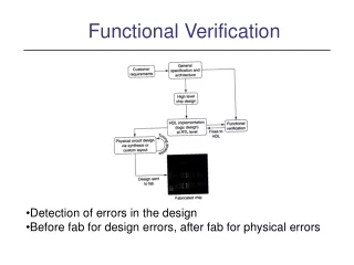
Act of ensuring correctness of the logic design • Also called: • Simulation • logic verification What is functional verification?
Architecture CPI Performance Verification Functional Verification Implementation in VHDL Timing Verification Logic Equival. Verification Cycle Time Tape-Out (Fabrication) What is Verification High Level Design
How do we know that a design is correct? • How do we know that the design behaves as expected? • How do we know we have checked everything? • How do we deal with size increases of designs faster than tools performance? • How do we get correct Hardware for the first RIT? Verification Challenge
Testpattern Design under Test Reference Model Results Checking • Also called: • Simulation • logic verification • Verification is based on • Testpattern Generation • Reference Model Development • Result Checking Answer: Functional Verification
Product time-to-market • hardware turn-around time • volume of "bugs" • Development costs • "Early User Hardware" (EUH) Why do functional verification?
Facilities: a general term for named wires (or signals) and latches. Facilities feed gates (and/or/nand/nor/invert, etc) which feed other facilities. • EDA: Engineering Design Automation--Tool vendors. IBM has an internal EDA organization that supplies tools. We also procure tools from external companies. Some lingo
Behavioral: Code written to perform the function of logic on the interface of the design-under-test • Macro: 1. A behavioral 2. A piece of logic • Driver: Code written to manipulate the inputs of the design-under-test. The driver understands the interface protocols. • Checker: Code written to verify the outputs of the design-under-test. A checker may have some knowledge of what the driver has done. A check must also verify interface protocol compliance. More lingo
Snoop/Monitor: Code that watches interfaces or internal signals to help the checkers perform correctly. Also used to help drivers be more devious. • Architecture: Design criteria as seen by the customer. The design's architecture is specified in documents (e.g. POPS, Book 4, Infiniband, etc), and the design must be compliant with this specification. • Microarchitecture: The design's implementation. Microarchitecture refers to the constructs that are used in the design, such as pipelines, caches, etc. Still more lingo
Verification Cycle Develop environment Create Testplan Debug hardware Escape Analysis Regression Hardware debug Fabrication
Team leaders work with design leaders to create a verification testplan. The testplan includes: • Schedule • Specific tests and methods by simulation level • Required tools • Input criteria • Completion criteria • What is expected to be found with each test/level • What's not covered by each test/level Verification Testplan
System ... Chip Unit Macro Hierarchical Design Allows design team to break system down into logical and comprehendable components. Also allows for repeatable components.
Only lowest level macros contain latches and combinatorial logic (gates) • Work gets done at these levels • All upper layers contain wiring connections only • Off chip connections are C4 pins Hierarchical design
Designer Level sim • Verification of a macro (or a few small macros) • Unit Level sim • Verification of a group of macros • Element Level sim • Verification of a entire logical function such as a processor, storage controller or I/O control • Currently synonomous with a chip • System Level sim • Multiple chip verification • Often utilizes a mini operating system Current Practices for Verifying a System
Some piece of logic design written in VHDL Inputs Outputs The Black Box • The black box has inputs, outputs, and performs some function. • The function may be well documented...or not. • To verify a black box, you need to understand the function and be able to predict the outputs based on the inputs. • The black box can be a full system, a chip, a unit of a chip, or a single macro.
White box verification means that the internal facilities are visible and utilized by the testcase driver. • Examples: 0-in (vendor) methods • Grey box verification means that a limited number of facilities are utilized in a mostly black-box environment. • Example: Most environments! Prediction of correct results on the interface is occasionally impossible without viewing and internal signal. White box/Grey box
To fully verify a black box, you must show that the logic works correctly for all combinations of inputs. This entails: • Driving all permutations on the input lines • Checking for proper results in all cases Full verification is not practical on large pieces of designs...but the principles are valid across all verification. Perfect Verification
Every macro would have perfect verification performed • All permutations would be verified based on legal inputs • All outputs checked on the small chunks of the design • Unit, chip, and system level would then only need to verify interconnections • Ensure that designers used correct Input/Output assumptions and protocols In an Ideal World....
Macro verification across an entire system is not feasible for the business • There may be over 400 macros on a chip, which would require about 200 verification engineers! • That number of skilled verification engineers does not exist • The business can't support the development expense • Verification Leaders must make reasonable trade-offs • Concentrate on Unit level • Designer level on riskiest macros Reality Check
Checklist of items that must be completed before RIT • Verification items, along with Physical/Circuit design criteria, etc • Verification criteria is based on • Function tested • Bug rates • Coverage data • Clean regression Tape-Out Criteria
Escape analysis is a critical part of the verification process • Important data: • Fully understand bug! Reproduce in sim if possible • Lack of repro means fix cannot be verified • Could misunderstand the bug • Why did the bug escape simulation? • Process update to avoid similar escapes in future (plug the hole!) Escape Analysis
We currently classify all escapes under two views • Verification view • What areas are the complexities that allowed the escape? • Cache Set-up, Cycle dependency, Configuration dependency, Sequence complexity, and expected results • Design View • What was wrong with the logic? • Logic hole, data/logic out of synch, bad control reset, wrong spec, Bad logic Escape Analysis: Classification
$ Time • The longer a bug goes undetected, the more expensive the fix • A bug found early (designer sim) has little cost • Finding a bug at Chip or System Sim has moderate cost • Requires more debug time and problem isolation • Could require new algorithm, which could effect schedule and cause rework of physical design • Finding a bug in System Test (testfloor) requires new hardware RIT • Finding a bug in the customer's environment can cost hundreds of millions in hardware and brand image Cost of Bugs Over Time
Secret of Verification (Verification Mindset)
The Art of Verification • Two simple questions • Am I driving all possible input scenarios? • How will I know when it fails?
Three Simulation Commandments Thou shalt stress thine logic harder than it will ever be stressed again Thou shalt not move onto a higher platform until the bug rate has dropped off Thou shalt place checking upon all things
The verification engineer should not be an individual who participated in logic design of the DUT • Blinders: If a designer didn't think of a failing scenario when creating the logic, how will he/she create a test for that case? • However, a designer should do some verification on his/her design before exposing it to the verification team • Independent Verification Engineer needs to understand the intended function and the interface protocols, but not necessarily the implementation Need for Independent Verification
DO: • Talk to designers about the function and understand the design first, but then • Try to think of situations the designer might have missed • Focus on exotic scenarios and situations • e.g try to fill all queues while the design is done in a way to avoid any buffer full conditions • Focus on multiple events at the same time Verification Do's and Don'ts
Try everything that is not explicitly forbidden • Spend time thinking about all the pieces that you need to verify • Talk to "other" designers about the signals that interface to your design-under-test • Don't: • Rely on the designer's word for input/output specification • Allow RIT Criteria to bend for sake of schedule Verification Do's and Don'ts (continued)
Checking framework Scoreboard Struct: Header Payload checking xlate predict DUT (bridge chip) Bus gen packet drive packet post packet Conv- ersation Errors Sequence Packet Protocol Typical Verification diagram Coverage Data Stimulus Device types FSMs latency conditions address transactions sequences transitions
Escape: A problem that is found on the test floor and therefore has escaped the verification process • The Line Delete escape was a problem on the H2 machine • S/390 Bipolar, 1991 • Escape shows example of how a verification engineer needs to think The Line Delete Escape
Line Delete is a method of circumventing bad cells of a large memory array or cache array • An array mapping allows for removal of defective cells for usable space The Line Delete Escape (pg 2)
05 . . . The Line Delete Escape (pg 3) If a line in an array has multiple bad bits (a single bit usually goes unnoticed due to ECC-error correction codes), the line can be taken "out of service". In the array pictured, row 05 has a bad congruence class entry.
Data in ECC Logic 05 . . . ECC Logic Counters Data out The Line Delete Escape (pg 4) Data enters ECC creation logic prior to storage into the array. When read out, the ECC logic corrects single bit errors and tags Uncorrectable Errors (UEs), and increments a counter corresponding to the row and congruence class.
ECC Logic 05 . . . ECC Logic Counters Threshhold Service Controller The Line Delete Escape (pg 5) When a preset threshhold of UEs are detected from a array cell, the service controller is informed that a line delete operation is needed. Data in Data out
Data in ECC Logic Line delete control Storage Controller configuration registers 05 . . . ECC Logic Counters Data out Threshhold Service Controller The Line Delete Escape (pg 6) The Service controller can update the configuration registers, ordering a line delete to occur. When the configuration registers are written, the line delete controls are engaged and writes to row 5, congruence class 'C' cease. However, because three other cells remain good in this congruence class, the sole repercussion of the line delete is a slight decline in performance.
Data in ECC Logic Line delete control Storage Controller configuration registers 05 . . . ECC Logic Counters Threshhold Service Controller The Line Delete Escape (pg 7) How would we test this logic? What must occur in the testcase? What checking must we implement? Data out
Testcase Driver Testcase Simulator Environment Data Output Model Design Source General Simulation Environment Compiler (not always required) C/C++ HDL Testbenches Specman e Synopsis' VERA Event simulator Cycle simulator Emulator Initialization Run-time requirements Testcase results Event Simulation compiler Cycle simulation compiler .... Emulator Compiler VHDL Verilog
Run Foreground Simulation Run Background Simulation Configure Environment Release Environment Debug Fail Debug Environment View Trace Monitor Batch Simulation Specify Batch Simulation Answer Defect Redirect Defect Verify Defect Fix Regress Fails Create Defect Define Project Goals Release Model Project Status Report Transfer Testcase Logic Designer Environment Developer Verification Engineer Model Builder Project Manager
Event Simulators • Model Technology's (MTI) VSIM is most common • capable of simulating analog logic and delays • Cycle Simulators • For clocked, digital designs only • Model is compiled and signals are "ordered". Infinite loops are flagged during compile as "signal ordering deadlocks". Each signal is evaluated once per cycle, and latches are set for the next cycle based on the final signal value. Types of Simulators
Simulation Farm • Multiple computers are used in parallel for simulation • Acceleration Engines/Emulators • Quickturn, IKOS, AXIS..... • Custom designed for simulation speed (parallelized) • Accel vs. Emulation • True emulation connects to some real, in-line hardware • Real software eliminates need for special testcase Types of Simulators (con't)
Influencing Factors: • Hardware Platform • Frequency, Memory, ... • Model content • Size, Activity, ... • Interaction with Environment • Model load time • Testpattern • Network utilization Relative Speed of different Simulators Speed compare Event Simulator 1 Cycle Simulator 20 Event driven cycle Simulator 50 Acceleration 1000 Emulation 100000
Cycle Sim for one processor chip • 1 sec realtime = 6 month • Sim Farm with a few hundred computers • 1 sec realtime = ~ 1 day • Accelerator/Emulator • 1 sec realtime = ~ 1 hour Speed - What is fast?
Clocking cycles • A simulator has the concept of time. • Event sim uses the smallest increment of time in the target technology • All other sim environments use a single cycle • A testcase controls the clocking of cycles (movement of time) • All APIs include a clock statement • Example: "Clock(n)", where n is the increment to clock (usually '1') Basic Testcase/Model Interface: Clocking Cycle 0 Cycle 1 Cycle 2 ... ....Cycle n
Setfac address_bus(0:31) "0F3D7249"x • Setting facilities • A simulator API allows you to alter the value of facilities • Used most often for driving inputs • Can be used to alter internal latches or signals • Can set a single bit or multi-bit facility • values can be 0,1, or possibly X, high impedence, etc • Example syntax: "Setfac facility_name value" Basic Testcase/Model Interface: Setfac/Putfac Cycle 0 Cycle 1 Cycle 2 ... ....Cycle n