Download
1 / 25
260 likes | 493 Views
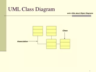
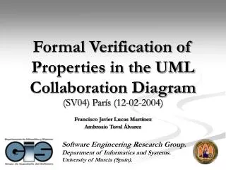
Formal Verification of Properties in the UML Collaboration Diagram. (SV04) París (12-02-2004) Francisco Javier Lucas Martínez Ambrosio Toval Álvarez. Index. Introduction Formalizing the UML Collaboration Diagram Features Elements Complete Diagram Formal Verification Properties

E N D
Formal Verification of Properties in the UML Collaboration Diagram (SV04) París (12-02-2004) Francisco Javier Lucas Martínez Ambrosio Toval Álvarez
Index • Introduction • Formalizing the UML Collaboration Diagram • Features • Elements • Complete Diagram • Formal Verification Properties • Conclusion and Further Work
Introduction (I) • UML: • Notation used to describe OO systems • Adopted by OMG • Imprecision in the UML Specification • Error introduced by modellers • Formalize UML metamodel: • Formal representation of any system expressed in UML notation • Verify properties on UML diagrams • Make precise transformations Solution: the use of formal languages
Introduction (II) • MDA: • Models guide the whole development process • Models with different levels of abstraction (PIM, PSM) • Goals achieved: portability, interoperability and reusability • Very important ensure PIM correction • Use of formalisms to guarantee that the PIM is correct • Transformations (PIM PSM, PSM PSM,…) • Precise support for these transformations
redisplay() window :Controller :Window <<parameter>> window 1: displayPositions(window) 1.1.3.1: add(self) contents {new} 1.1 *[1..n]: drawSegment(i) wire <<local>> line wire: Wire :Line {new} 1.1.2: create(r0, r1) <<self>> i-1 i 1.1.3: display(window) 1.1.1a: r0:=position() 1.1.1b: r1:=position() left: Bead right:Bead Formalization of UML Collaboration Diagram. Features • One of the UML Interaction Diagram • Shows • Interaction between objects • Context
ClassifierRoles <<local>> line wire: Wire :Line {new} Formalization of UML Collaboration Diagram. Elements (I) • ClassifierRoles • Represents the objects which participates in the collaboration • Format Label: ‘/’ RoleName : ClassifierName [ ‘,’ ClassifierName]* • RoleName, shows the role that object plays in the collaboration • ClassifierName, which indicates the class whose the objetc belongs to • Maker ({new}, {destroyed}, {transient}) (fmod CLASSIFIERROLE is sorts ClassifierRole RoleName . ... op classifierRole : RoleName Marker ClassName -> ClassifierRole . op getRoleName : ClassifierRole -> RoleName . op getMarker : ClassifierRole -> Marker . op getClassName : ClassifierRole -> ClassName . ... endfm)
<<local>> line wire: Wire :Line {new} AssociationRoles Formalization of UML Collaboration Diagram. Elements (II) • AssociationRoles • It links two ClassifierRoles • Can have a name (Label), arrows that indicate the navigability and marks (fmod ASSOCIATIONROLES is sort AssociationRoles . ... op nullAssocRoles : -> AssociationRoles . op associationRoles : ClassifierRole ClassifierRole Label Marker -> AssociationRoles . op getCR1 : AssociationRoles -> ClassifierRole . ... endfm)
Formalization of UML Collaboration Diagram. Elements (III) • Messages, indicates the invoking of a method of a ClassifierRole that is invoked from another ClassifierRole • Messages, elements: • Action, which defines the different kinds of actions that can occur as answers to a message. Seven kinds of actions (CallAction,…) • MessageType, indicates what kind of communication has been made. There are 3 main kind of Messages Types: • ProcedureCall • ReturnFromCall • Asynchronous • 2 ClassifierRoles, sender and receiver from the message. • ArrowLabel, which is the label of the message.
Formalization of UML Collaboration Diagram. Elements (IV) • Messages, format of the ArrowLabel: predecesor sequence-expression return-value := message-name argument-list • Sequence-expression, two parts: • Sequencenumber identifies the message. • Recurrence is used to indicate a condition or an iteration
Formalization of UML Collaboration Diagram. Elements (V) • Messages, formalization: (fmod ARROWLABEL is sort ArrowLabel . ... *** Label = return value. op arrowLabel : Predecessors SequenceNumber Recurrence Label OpName ParamCallList -> ArrowLabel . endfm) (fmod MESSAGE is sorts Message . ... op message : MessageType ArrowLabel Constraint ClassifierRole ClassifierRole Action -> Message . op getMsgType : Message -> MessageType . op getMsgArrowLabel : Message -> ArrowLabel . ... op getMsgRecurrence : Message -> Recurrence . ... endfm)
1: closePhases() :System Multi-objet :Director 2: closePhases() p: Project :Phase 3: close() Formalization of UML Collaboration Diagram. Elements (and VI) • MultiObjects • Represents a set of objects • A message sent to a multiobject turns into two messages: • One that is the iteration to the set and • other that is the stimulus sent to each individual object (fmod MULTIOBJECT is sort MultiObject . ... op multiObject : ClassifierRole ObjectList -> MultiObject [ ctor ] . op nullMultiObject : -> MultiObject . ... endfm)
Formalization of UML Collaboration Diagram. Complete Diagram • Two elements appear: • InteractionInstanceSet contains messages that a ClassifierRole sends or receives • InstanceRole represents a ClassifierRole and its InteractionInstanceSet (fmod INTERACTIONINSTANCESET is protecting MESSAGELIST * (sort MessageList to InteractionInstanceSet) . endfm) (fmod INSTANCEROLE is sort InstanceRole . ... op instanceRole : ClassifierRole InteractionInstanceSet -> InstanceRole . ... endfm) (fmod COLLABORATIONDIAG is sort CollaborationDiag . ... op collaborationDiag : AssociationRolesList InstanceRoleList MultiObjectList -> CollaborationDiag . ... endfm)
1: closePhases() :System :Director 2: closePhases() p: Project 3: close() :Phase Formalization of UML Collaboration Diagram. Example (I) • UML CASE tool:
Formalization of UML Collaboration Diagram. Example (II) • Algebraic specification: (fmod CLOSEPHASE is ... op CDClosePhase : -> CollaborationDiag . op MultiPhase : -> Object . ops Director System Project Phase : -> ClassName . ops director system Project phase : -> ClassifierRole . ... eq director = classifierRole ('director, nullMarker, 'Director) . eq system = classifierRole ('system, nullMarker, 'System) . eq project = classifierRole ('p, nullMarker, 'Project) . eq phase = classifierRole ('phase, nullMarker, 'Phase) . *** InstanceRoleList. eq instanceRList = instanceRole(director, message(ProcedureCall, arrowLabel(nullPredecessors,1 ;, nullRecurrence, nullLabel,'closePhase, nullParamCall), constrainMsg, director, system, CallAction) ) ... instanceRole(phase,... ) . *** Associations and Multiobject. eq assoRList = associationRoles (director,system,'label_dir_sist, nullMarker) associationRoles (system, project, 'label_sist_project, nullMarker) associationRoles (project, phase, 'label_proy_fase, nullMarker) . eq multiObjList = multiObject (phase, MultiPhase) . *** Diagram. eq CDClosePhase = collaborationDiag (assoRList, instanceRList, multiObjList) . endfm)
1: closePhases() :System :Director 2: closePhases() p: Project 3: close() :Phase Formalization of UML Collaboration Diagram. Example (III) • Maude Reduction: reduce in CLOSEPHASE : CDClosePhase result CollaborationDiag : collaborationDiag( *** AssociationRolesList. associationRoles( classifierRole('director,…), classifierRole('system,…), 'label_dir_sist,nullMarker)…, *** InstanceRoleList. instanceRole(classifierRole('director,…), message(ProcedureCall, arrowLabel(nullPredecessors, 1 ;,"noRecurrence", 'noLabel, ‘closePhase,nullParamCall), …))... *** MultiObjectList. multiObject( classifierRole(‘phase,…),MultiPhase))
Formal Verification of Properties (I) • Property: “at any moment the only objects that can send messages are those that have the flow of control ” • Assumptions during the execution of a program: • Flow of controls sequentially • The execution of a method starts at the beginning of method body and returns the control to the method that called it • The execution of two methods are: • Either non-overlapping • Or nested
Formal Verification of Properties (II) • We can represent the way that flow of control goes in and goes out of the method invocation as a tree: • Each method is represented by a node • The root represents the main method • M1 is the parent of M2 if control flows from M1 to M2 (nested execution), and • M1 is to the left of M2 if the flow of control leaves from M1 before M2 is called (non-overlapping execution)
1: addUser(name, tlf) 2: s := new (name,tlf) :Office s: User :Manager 3: addUser(s) :usersStore 3 2 User usersStore 1 1 Office Office Manager Manager Formal Verification of Properties (III) • The flow of control corresponds to a depth-first traversal of this tree. And it can be implemented as a stack which has the following behaviour: • When a method execution begins, we push it onto the stack • The method will leave the stack when its execution finishes • Example. • new, state of the stack, • addUser, • We have a similar stack but with the possible senders of messages: • new • addUser • In each moment, these are the only possible senders. That is the property that we want to verify
1: addUser(name, tlf) 2: s := new (name,tlf) :Office s: User usersStore Office :Manager Manager 3: addUser(s) 4: updateBalance() :usersStore Formal Verification of Properties (IV) • Example that breaks the property that we are verifying: • If method 3 is executing… • …the next message will be the method 4 • But in that moment, the possible senders are: • Manager – Office – usersStore • The sender of method 4 is User. This is not possible, thus the example is erroneous
Formal Verification of Properties (and V) (fmod PROPERTY is ... op testProp : CollaborationDiag -> String . *** RolesList = possible senders. *** InteractionInstanceSet = messages that have yet been invoked. op testProp : ClassifierRoleList InteractionInstanceSet -> String . ... *** The possible senders are the sender and the receiver of the first message. eq testProp(CD) = testProp(getMsgSender(head (getCDMessages (CD))) getMsgReceiver(head (getCDMessages (CD))), tail(getCDMessages (CD))) . eq testProp(CRL, empty) = "" . eq testProp(CRL, M IIS) = if is getMsgSender(M) in CRL then *** The forbibben senders are behind M and are eliminated. testProp((clean(CRL, getMsgSender(M)) getMsgReceiver(M)), IIS) else "ERROR: Spontaneous message: " + string(getMsgNumber(M)) fi . endfm) reduce in ADDUSER : testProp(DCAddUser) result String : "ERROR: Spontaneous message: \004. "
Conclusions and Further Work • Algebraic specification for the UML Collaboration Diagram has been carried out. It facilitates: • Building prototypes, thanks to the use of Maude • Offers the basis to: • Check that models verify certain properties • Precise transformations • Simple: Collaboration Diagram Sequence Diagram (made) • Complex: Class Diagram Collaboration Diagram (on going) • Suitable to MDA • Integrated with the specifications realized in paper [2]: • Class Diagram: guarantee the consistency between Class and Collaboration Diagram (made) • Statecharts Diagram: simulation
Formal Verification of Properties in the UML Collaboration Diagram (SV04) París (12-02-2004) Francisco Javier Lucas Martínez Ambrosio Toval Álvarez
References (I) [1] OMG(2001). “UML Specification 1.5”. www.omg.org [2] José Luís Fernández Alemán (2002). “Una propuesta de formalización de la arquitectura en cuatro capas de UML”. Tesis Doctoral. Departamento de Informática y Sistemas, Universidad de Murcia. [3] Ambrosio Toval, José Luís Fernández Alemán. "Improving System Reliability via Rigorous Software Modeling: The UML Case", Proceedings of the 2001 IEEE Aerospace Conference (track 10: Software and Computing), Montana, USA IEEE Computer Society March 10-17, 2001 [4] José Ramón Hoyos Barceló, J. L. Fernández Alemán, Ambrosio Toval Álvarez. “Transformaciones en los Diagramas de .Secuencia de UML”. Taller de Desarrollo de Software Preciso, en conjunción con VI Jornadas de Ingeniería del Software y Bases de Datos (JISBD’01) Departamento de Informática. Universidad de Castilla-La Mancha, Almagro (Ciudad Real). 21-23 Noviembre 2001. [5] Ambrosio Toval, José Sáez, Francisco Maestre. "Automated property verification in UML models". AVoCS 2003: Third Workshop on Automated Verification of Critical Systems, Southampton (UK) 2-3 Abril, 2003. http://www.dsse.ecs.soton.ac.uk/techreports/2003/avocs03/.
References (II) [6] Manuel Clavel, Francisco Durán, Steven Eker, Patrick Lincoln, Narciso Martí-Oliet, José Meseguer, Carolyn Talcote (2003). “Maude 2.0 Manual. Versión 1.0”. Web: http://maude.csl.sri.com/ [7] OMG(2001). “MDA Guide Version 1.0.1”. www.omg.org [8] Jon Whittle, João Araújo, Ambrosio Toval and J.L. Fernández Alemán. "Rigorously Automating Transformations of UML Behavior Models" Dynamic Behaviour in UML Models: Semantic Questions in conjunction with UML 2000 York, UK , ACM SIGSOFT, IEEE Computer Society. October 2-6 2000 http://www.disi.unige.it/person/ReggioG/UMLWORKSHOP/INDEX.html [9] João Araújo, Jonathan Whittle, Ambrosio Toval, and Robert France. “Integration and Transformation of UML Models”. Object-Oriented Technology: ECOOP 2002 Workshop Reader J. Hernandez, A. Moreira (eds.), Lecture Notes in Computer Science, vol. 2548, pp.184-191, Springer-Verlag, 2002 [10] Francisco Javier Lucas Martínez, Ambrosio Toval Álvarez. “Formal Verification of Properties in the UML Collaboration Diagram”. ICSSEA 2004: 3rd Workshop on SYSTEM TESTING AND VALIDATION. December 2004. [11] Francisco Javier Lucas Martínez, Ambrosio Toval Álvarez. “Verificación Formal de Propiedades y Transformaciones en el Diagrama de Colaboraciones de UML”. DYNAMICA 2004.
References (and III) [12] Johan Litius, Iván Porres Paltor. “vUML: a Tool for Verifying UML Models”. 14th IEEE International Conference on Automated Software Engineering, October 1999. [13] Ninh-Thuan Truong, Jeanine Souquieres. “An approach for the verification of UML models using B”. 11th IEEE International Conference and Workshop on the Engineering of Computer-Based Systems (ECBS'04) May 2004. [14] Soon-Kyeong Kim, David Carrington. “A Formal Object-Oriented Approach to defining Consistency Constraints for UML Models”. 2004 Australian Software Engineering Conference (ASWEC'04) Abril 2004.