0 likes | 13 Views
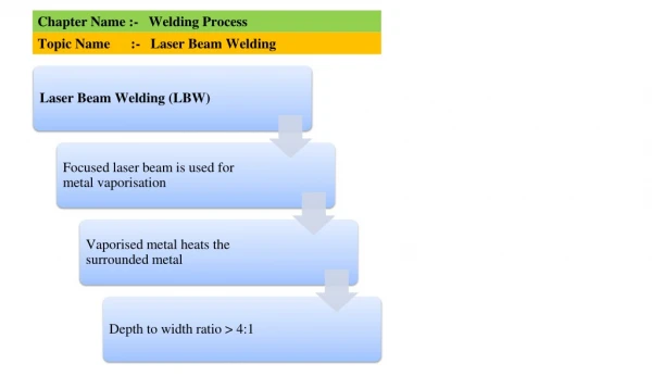
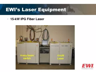
Laser beam machining utilizes coherent light beams to cut, drill, weld, and modify materials with high precision and speed. The process involves a ruby crystal, xenon flash tube, cooling system, and focusing lens to generate a concentrated laser beam. By adjusting power density and interaction time, lasers can perform various tasks including welding, cutting, and heat treating on a wide range of materials. Though offering advantages like precision and automation, laser machining also has drawbacks such as high cost and limited metal removal rates.
E N D
Laser Beam Machining (Light Amplification by Stimulated Emission of Radiation) 1
PROCESS PRINCIPLES • Laser machining utilizes the energy from coherent beams of light to remove, melt, or thermally modify materials. • Not only are lasers able to cut, drill, and weld, but they are also used to mark parts, heat treat surfaces. • Most laser users implement the process to take advantage of the laser's very high processing speeds, low thermal effect on the work piece, and automation. its applicability to 2
a) Ruby crystal • The cylindrical shaped ruby crystal forms the important part of the laser beam equipment. • Ruby is aluminum oxide with chromium dispersed throughout it. • Both the ends of the ruby crystal are made absolutely parallel to each other. 4
• One of the end faces of the crystal is highly silvered, so that it reflects nearly 96% of the incident light. • In order to tap the laser output, the other end face of the crystal is partially silvered and contains a small hole through which the laser beam emerges. 5
b)Xenon flash tube • The ruby crystal is surrounded by a helical flash tube containing inert gas xenon. • The flash tube is connected to a pulsed high voltage source xenon transforms the electrical energy into white light flashes (light energy). by which the 6
c)Cooling system • A cooling system, which utilizes water, air or liquid nitrogen, is provided to protect the ruby crystal from the enormous amount of heat generated. 7
d)Focusing lens • The light beam or laser beam, which escapes through the tiny hole of the ruby crystal possess low power densities. • The beam is useless for material processing applications until its increased. • This is achieved by means of a focusing lens. The lens focuses the laser beam to converge to a narrow increasing its power density. power density is spot thereby 8
LBM Operation • In operation, when the xenon flash tube is connected to a pulsed high voltage source, the inert gas xenon transforms the electrical energy into white light flashes (light energy). • Since the ruby crystal is exposed to the intense light flashes, the chromium atoms of the crystal are excited and jumped to a high- energy level. 9
• These chromium atoms immediately drop to an intermediate energy level with the evolution eventually drop back to their original state with the evolution of a discrete quantity of radiation in the form of red fluorescent light. • As the red light emitted by one excited atom hits another excited atom, the second atom gives off red light, which is in phase with the colliding red light wave. of heat and 10
• The effect is enhanced as the silvered ends of the ruby crystal cause the red light to reflect back and forth along the length of the crystal. • The chain reaction collisions between the red light wave and the chromium atoms become so numerous that, finally the total energy bursts and escapes through the tiny hole as a laser beam. • The beam is focused with a simple lens to obtain high power densities in small areas of the work surface. 11
• The intense heat of the laser beam is used to melt and, or evaporate the work piece material being cut. • A stream of gas, like oxygen, nitrogen or argon is often used to blow the molten metal through the cut, cool the work piece and minimize the heat affected zone. • The type of gas used depends on the work piece material being cut. 12
• Oxygen is used for mild steel work pieces; nitrogen or oxygen for stainless steel; nitrogen for aluminum, and inert gas like argon for titanium metals. • The table carrying the work piece can be moved in three dimensions with respect to the laser beam to obtain the desired profile of cut on the work piece. 13
Process Parameters of LBM • Power density and laser beam-work piece interaction time are the most important variables determining whether the beam will weld, cut, mark or heat treat. • For rapid heating of a surface without melting, a highly focused beam producing power densities of only 1.5x10²- 1.5xl04w/ cm2is used. 14
• If melting is desired, as in the case of welding or cladding applications, power densities ranging from 1.5 x 10⁴- 1.5 x 10⁵W cm2is used. • Cutting and drilling action will occur for power densities ranging from 1.5 x 10⁶- 1.5 x 10⁸W cm2. 15
ADVANTAGES OF LBM: • Any material, including non-metals, and irrespective of their hardness and brittleness can be machined by laser. • Apart from cutting, drilling and welding materials, lasers can also be used for marking, scribing, heat- treating of surfaces and selectively clad materials. 16
• The process can be easily automated • Can remove material in very small amounts • Laser beam machining is a force-less machining process. This allows very thin and fragile parts to be easily cut. 17
DISADVANTAGES OF LBM • Costlier • Low thermal efficiency • Low metal removal rates • Process is limited to thin parts • High reflectivity materials are difficult to machine • Difficult to drill exact round holes 18
APPLICATIONS OF LBM • Laser beam perform precision micro- machining on all materials such as steel, ceramic, glass, diamond, graphite etc. it is used for cutting, drilling, materials, marking, treating of surfaces and selectively clad materials. machining is used to welding scribing, of heat 19
ELECTRON BEAM MACHINING (EBM) 20
ELECTRON BEAM MACHINING (EBM) WORKING PRINCIPLE:- • Electron beam machining (EBM) process is classified into two categories 'Thermal type' and 'Non-thermal type'. • In the thermal type EBM process, the surface of thermo electronic cathode is heated to such a high temperature that the electrons acquire sufficient speed to escape out to the space around the cathode. 21
• The stream of these large number of electrons moves as a small diameter beam of electrons towards the anode. • As a result, the work piece is heated by the bombardment of these electrons in a localized area, to such a high temperature that it is melted and vaporized at the point of bombardment. • In the second type (non-thermal EBM) process, the electron beam is used to cause a chemical reaction. 22
• When the high velocity beam of electrons strikes the work piece, the kinetic energy of electrons converts into heat which is responsible for melting and vaporization of work piece material. • This process can produce any shape of hole; however, round holes are usually drilled in metals, ceramics, plastics, etc. • It can machine electrically conducting as well as non-conducting materials. Before machining starts, vacuum is created in the machining chamber. 23
• The diameter of the electron beam focused onto the work should be slightly smaller than the desired hole diameter. • As the electron beam strikes the work- piece, the material gets heated, melted and partly vaporized. • On the exit side of the hole, the synthetic or organic backing material is used. 24
• The electron beam after complete penetration into the work piece, also partly penetrates in the auxiliary backing material. The backing material vaporizes and comes out of hole at a high pressure. • The molten material is also expelled along with the vaporized backing material. 25
• In case of a non-circular hole to be produced, the electron beam is deflected with the help of the computer control, along the perimeter of the hole to be produced. • As an alternative method, the beam can be kept stationary but the work-table can be moved in the desired path with the help of CNC. 26
ELECTRON BEAM MACHINING SYSTEM • There are three important elements of EBM system, viz • Vacuum system, • Electron beam gun • Power supply. 27
High Voltage lead Cathode Grid Optical Viewing Stream of Electrons Magnetic Lens Deflection Coils Work Table To Vacuum Pump Schematic diagram of EBM system. 28
(i) Electron Beam Gun:- • It is used to produce electron beam of the desired shape and to focus at the predetermined location. • EBM gun is operated in the pulsed mode. A super heated cathode (tungsten filament type) generates the electrons cloud. • Sometimes cathode may be used as a solid block indirectly heated by radiation emitted from a filament. 29
• Due to force of repulsion from the cathode, electrons move at a very high acceleration towards the anode which attracts them. • The velocity with which electrons pass through the anode is approximately 66% that of light. • On the path of electrons, there is a kind of switch (bias electrode) which generates the pulses. 30
• A magnetic lens is used to shape the electron beam into a converging beam. This beam is passed through a variable aperture to reduce the diameter of the focused beam by removing the stray electrons. • Magnetic lenses are used to pin point the location of the beam, deflect it, and make it a round beam falling on the workpiece. 31
(ii) Power Supply:- • The power supply generates a voltage as high as 150 kV to accelerate electrons. The EBM gun of a powerful system is usually operated at about 12 kW and an individual pulse energy as 120 J/pulse. • The power density at the work surface is too high that is why it is capable to melt and vaporize the work piece material. Thus, material removal in EBM is basically due to vaporization. 32
(iii) Vacuum System and Machining Chamber:- • The electron beam generation, its travel in the space, and resulting machining take place in a vacuum chamber. • The vacuum does not allow rapid oxidation of incandescent filament and there is no loss of energy of electrons as a result of collision with air molecules. 33
PROCESS PARAMETERS The important parameters in EBM process are • Beam current, • Duration of pulse, • Lens current • Signals for the deflection of beam. The values of these parameters during EBM are controlled with the help of a computer. 34
• Beam current varies from 100 uA to 1A and it governs the energy/pulse being supplied to the workpiece. • Higher the energy/pulse more rapidly the hole can be drilled. Pulse duration during EBM varies in the range of 50 us to 10 ms depending upon the depth and diameter of the hole to be drilled. • Drilling using longer pulse duration results in a wider and deeper drilled hole. It also affects HAZ as well as the thickness of the recast layer which is normally 0.025 mm or less. The extent of both these effects should be minimum possible. 35
• The working distance (i.e. the distance between the electron beam gun and the focal point) and the focused beam size (diameter) are determined by the magnitude of lens current. • The shape of the hole along its axis (straight, tapered, etc.) is determined by the position of the focal point below the top surface of the workpiece. • To obtain the hole shape other than circular, the movement of the beam can be programmed. 36
• The material removal rate (MRR) at which the workpiece material is vaporized can be calculated from following equation MRR = n x p /w where, n is the cutting efficiency, p is the power (J/s) and w is the specific energy (J/cm3) required to vaporize the work-material. 37
• Specific energy (W) can be calculated as follows: W =Cps(Tm – Ti) + Cpl x (Tb – Tm) + Hf + Hv • where, CP is specific heat, Tm is melting temperature, Ti is initial temperature of workpiece, Tb is boiling temperature Hf is latent heat of fusion, and Hv is the latent heat of vaporization. The cutting efficiency is usually below 20%. Here, CP is assumed constant although it varies with temperature. Suffix s and l indicate solid and liquid states, respectively. 38
CHARACTERISTICS OF THE PROCESS • This process can be used to machine both electrically conductive as well as non- conductive materials, viz Ni, Cu, Al, ceramics, leather, plastics, etc. It has been observed that at the entry side of the electron beam, a small sized burr (a solidified layer) may be left out. • In general, performance (viz MRR) of the EBM process is not significantly influenced by the properties (physical, mechanical and metallurgical) of workpiece material. 39
• This process can machine small diameter holes (0.1 to 1.4 mm) to a large depth (say, 10 mm) or in other words, a hole with high aspect ratio (up to 15:1). • The geometry of the hole and depth of the hole to be drilled, determine the average machining rate (or penetration rate). • No mechanical force is applied on the job; hence fragile (or brittle), thin, and/or low strength workpieces can be easily machined. Off-the-axis holes (or inclined holes) can also be machined by this process. 40
Advantages of EBM This process can machine small diameter holes (0.1 to 1.4 mm) to a large depth (say, 10 mm) or in other words, a hole with high aspect ratio (up to 15:1). This process can be used to machine both electrically conductive as well as non-conductive materials. No mechanical force is applied on the job; hence fragile (or brittle), thin, and/or low strength workpieces can be easily machined. Off-the-axis holes (or inclined holes) can also be machined by this process. EBM process is not significantly influenced by the properties (physical, mechanical and metallurgical) of workpiece material. 1. 2. 3. 4. 41
Advantages of EBM 5. Depth of penetration and heat can be easily controlled 6. The operation is chemically clean. 7. Low heat input relative to the depth of penetration, leads to distortion free machining operation. 8. Hole location is very accurate. 42
Limitations of EBM 1. Very high temperature gradient would result in residual thermal stresses. Another limitation of the process is very high cost of the equipment. The operator also should be skilled one. The quality of the edges produced is determined by the thermal properties of the workpiece material and the pulse energy. The heat affected zone (HAZ) depends upon pulse duration and the diameter of the hole being drilled. Application of the process is possible only for specializeddrilling operations. For deeper penetrations vacuum is essential. 2. 3. 4. 5. 6. 7. 43
APPLICATIONS • EBM is more popular in industries like aerospace, insulation, food processing, chemical, clothing, etc. • It is very useful in those cases where number of holes (simple as well as complex shaped) required in a work piece may range from hundreds to thousands (perforation of sheets, etc). • This Process is also used for drilling thousands of holes (diameter < 1.00 mm) in very thin plates used for turbine engine combuston domes. • Many thousand holes (diameter < 1.0 mm) in a cobalt alloy fiber spinning head of thickness around 5 mm are drilled by EBM. 44
• This drilling is claimed to be 100 times faster than EDM. • Holes in the filters and screens used in food processing industries are also made by this process. • The applications of EBM also encompass the areas like making of fine gas orifices in space nuclear reactors, holes in wire drawing dies, cooling holes in turbine blades, metering holes in injector nozzles of diesel engines, etc. 45
• EBM is also being employed for pattern generation for integrated circuit fabrication. • In EBM, the beam power, focus, pulse duration and mechanical motion have been controlled numerically. This would permit more accurate and complex shaped machining using numerically controlled EBM system (NC-EBM). 46
Questions 1. Explain the working principle of EBM process. Make the necessary sketch. Can you machine electrically non-conducting materials using EBM process? How the work-table is protected from getting damaged by the electron beam which has completely penetrated the workpiece? How a complex shape can be cut using EBM process? Write an equation to compute specific energy of vaporization. Write four specific applications where you feel that EBM should be the preferable choice. 2. 3. 4. 5. 6. 47