Download
1 / 28
280 likes | 467 Views
G. Cheymol - M Gilbert – P.Y Thro LILM/SCP/DPC/DEN/CEA Saclay M. Petrarca CERN P Girardot and all SIS/IRFU/DSM/CEA Saclay. Laser beam for Califes. Global Scheme. Outlines. Pulse picker Frequency conversion Transport Conclusion. Pulse picker: scheme. The pulse picker is made with:

E N D
G. Cheymol - M Gilbert – P.Y Thro LILM/SCP/DPC/DEN/CEA Saclay M. Petrarca CERN P Girardot and all SIS/IRFU/DSM/CEA Saclay Laser beam for Califes DEPARTEMENT DE PHYSICO-CHIMIE DEN/Saclay
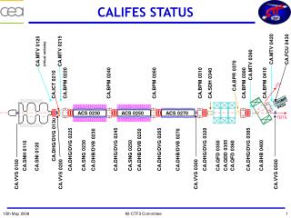
Global Scheme DEPARTEMENT DE PHYSICO-CHIMIE DEN/Saclay
Outlines • Pulse picker • Frequency conversion • Transport • Conclusion DEPARTEMENT DE PHYSICO-CHIMIE DEN/Saclay
Pulse picker: scheme • The pulse picker is made with: • 2 pockels cells (PC) • 3 polarisers • One PC sets the rising edge, the other sets the falling edge • Each pockels cell is triggered by a HV pulser • Both HV pulsers are triggered by a generator • Pulse picker • in test in Saclay Independant triggering allows to change the duration of the pulse selected DEPARTEMENT DE PHYSICO-CHIMIE DEN/Saclay
Related specifications HV pulse Pulse picker ordered to Leysop Ldt : specifications Transmission expected time diagram • Mains specifications for the pulse picker: • sharp rise time and fall time: less than 666ps ~ 400 ps • duration ~ 0.5 ns to 140 ns • with stability better than ± 1.5% • - low transmission (< 4%) out of the pulse selected • - need for high transmission during the pulse DEPARTEMENT DE PHYSICO-CHIMIE DEN/Saclay
Pulse picker: choise dry cell /fluid - transmission • Dry cell was finally preferred: • to avoid degradation of the fluid with peak irradiance, (especially for a long running time). • in spite of: • theoretically less impedance adaptation • less transmission (around 1% less per cell) • Finally, the measured transmission was about 92% per cell (a bit less than expected). • For entire pulse picker, at CERN: T~ 80%. DEPARTEMENT DE PHYSICO-CHIMIE DEN/Saclay
Pulse picker: Test Report–Temporal rise time Out of one pockel cell (optical): measured rise time: less than ~ 350ps Out of the pulser (trigerring) measured rise time ~260ps DEPARTEMENT DE PHYSICO-CHIMIE DEN/Saclay
Pulse picker: Test Report– Chopped pulse 100ns Duration Chopped Pulse DEPARTEMENT DE PHYSICO-CHIMIE DEN/Saclay
Chopped pulse – at CERN with a 60 GSamples/s oscilloscope Cell 1 alone (Cell 2 off) 20ns/div Gate 20 ns 20 ns/div Gate 20 ns 2ns/div Check of rising edge 500ps/div 1 pulse selected 1ns/div DEPARTEMENT DE PHYSICO-CHIMIE DEN/Saclay
2w TYPE I : e Optical axis o w 2w e w TYPE II : o Optical axis Frequency conversion – crystals considered • IR Green type II: KTP, LBO ; type I: BBO, LBO • Green UV type I: BBO, CLBO, KDP DEPARTEMENT DE PHYSICO-CHIMIE DEN/Saclay
Frequency conversion – 1047nm 523 nm - calculations Nominal parameters for optimisation: - entering beam parameters: 10µJ, 6ps, 1047 nm, M²(beam quality factor) =1 - CE (conversion efficiency) =35% ( 12% for -> 4) DEPARTEMENT DE PHYSICO-CHIMIE DEN/Saclay
Frequency conversion – 523 nm 262 nm - calculations Typical parameters and tolerances calculations for entering beam parameters: 3.5µJ, 4.9ps, 523 nm, M²(beam quality factor) =1 and for CE (conversion efficiency) =35% ( 12% for -> 4) DEPARTEMENT DE PHYSICO-CHIMIE DEN/Saclay
M² measured out of A2 amplifier Geometrical image of a plane around A2 Focused beam M²~ 2 (1.5 to 2.6) for the beam out of A2 DEPARTEMENT DE PHYSICO-CHIMIE DEN/Saclay
Frequency conversion – 1047523– simulation/measurements On KTP, with large margin on angular acceptance, we expect: conversion efficiency measured ~ conversion efficiency given by simulation. May 22nd 2008 ASE of the laser in between the micropulses DEPARTEMENT DE PHYSICO-CHIMIE DEN/Saclay
Frequency conversion – 523262 – large walk-off With low IR energy, the beam has to be focused a lot. -> walk off and angular acceptance limitations become very critical -> lack off conversion efficiency -> high distortion in the UV_near field profile. Oct 8th 2008 Conversion efficiency (green to UV) ~ 38% Energy (micropulse): IR:0.82µJ ; Gr:0.32µJ; UV: 0.12µJ Amp 1 alone (Dimension of the input green beam: 42µm x 112µm) DEPARTEMENT DE PHYSICO-CHIMIE DEN/Saclay
Frequency conversion – conclusion The focusing diameter on the crystal should be increased when the power increase. A stabilized IR beam should allow to optimise a “final” configuration. Optimized cylindrical focusing could be tested. Other crystal (KDP) could be tested DEPARTEMENT DE PHYSICO-CHIMIE DEN/Saclay
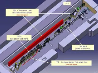
Transport- tables and mechanical supports DEPARTEMENT DE PHYSICO-CHIMIE DEN/Saclay
under air / under vacuum beam delivery • Consequence of Temperature and Pressure variations: • n-1 (~ 3.10-4) proportional to P et T. n: air optical index • l = 80m and ΔT or ΔP = 1% Δ (n .l) ~ 0.3mm Δt ~ 1 ps. • Attenuation (@ 262 nm): • Rayleigh Diffusion Transmission = 98%. • Ozone absorption: • = ~10-17 cm-2 (max at 255 nm). : absorption cross section • 40 ppb ozone, l= 80m T=92%. Transport under vacuum to be preferred Only the straight line under the roof in CTF2 + CLEX is put under vacuum. DEPARTEMENT DE PHYSICO-CHIMIE DEN/Saclay
ft d ft A’ A Optical relay /telescope disturbance Optical relay reduce consequences of mirror vibration, air turbulence in plane A’ (A’ geometrical image of A) 3 lenses telescope allows to: - decrease the footprint of the optical system for a given relay distance. - change zoom factor and relay distance (to some extent) DEPARTEMENT DE PHYSICO-CHIMIE DEN/Saclay
Long distance transport « under the roof », 2 telescopes (2lenses) transport the beam from the laser room to the photocathode 2 telescopes (2lenses) : L1-L2 with f~ 10 m L3-L4 with f~ 7.5m DEPARTEMENT DE PHYSICO-CHIMIE DEN/Saclay
Optical path on the Califes laser table DEPARTEMENT DE PHYSICO-CHIMIE DEN/Saclay
Optical path on the Califes laser table DEPARTEMENT DE PHYSICO-CHIMIE DEN/Saclay
« photoinjector » optical table Photoinjector DEPARTEMENT DE PHYSICO-CHIMIE DEN/Saclay
« photoinjector » optical table Photoinjector DEPARTEMENT DE PHYSICO-CHIMIE DEN/Saclay
Transport and sensing/ conclusion • Some lack of quality on UV components ordered. Many components tested and returned. - about 25 lenses, mirrors or windows between BBO and photocathode. Transmission should be 75 to 80% ( 85% measured between laser room and photoinjector table). - image transport perform well, but with great walk off on BBO, the image on the photocathode is distorted.- procedures for adjusting all systems have been provided. DEPARTEMENT DE PHYSICO-CHIMIE DEN/Saclay
General conclusion • Pulse picker, transport and various sensing perform quite well- Frequency conversion has still to be optimised with the IR laser beam working better. DEPARTEMENT DE PHYSICO-CHIMIE DEN/Saclay
Thank you for your attention DEPARTEMENT DE PHYSICO-CHIMIE DEN/Saclay
Pulse picker: how it works? In red: the different temporal shapes of the pulse Final shaped pulse DEPARTEMENT DE PHYSICO-CHIMIE DEN/Saclay