Download
1 / 21
210 likes | 264 Views
Learn about OpenGL drawing primitives, attributes, polygon faces, culling, hidden-surface removal, constructing 3D models, and collision detection. Explore various OpenGL features and the process of specifying colors, depth buffers, and geometric models. Discover polygon-scan conversion algorithms and essential techniques for drawing circles, cones, cylinders, and spheres in OpenGL.

E N D
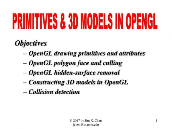
PRIMITIVES & 3D MODELS IN OPENGL Objectives • OpenGL drawing primitives and attributes • OpenGL polygon face and culling • OpenGL hidden-surface removal • Constructing 3D models in OpenGL • Collision detection @ 2017 by Jim X. Chen: jchen@cs.gmu.edu
OpenGL Drawing Primitives • gl.glDrawArrays(GL_POINTS, 0, 3); GL_POINTS, GL_LINE_STRIP, GL_LINE_LOOP, GL_LINES, GL_LINE_STRIP_ADJACENCY, GL_LINES_ADJACENCY, GL_TRIANGLE_STRIP, GL_TRIANGLE_FAN, GL_TRIANGLES, GL_TRIANGLE_STRIP_ADJACENCY, GL_TRIANGLES_ADJACENCY and GL_PATCHES @ 2017 by Jim X. Chen: jchen@cs.gmu.edu
The old way of doing it void glBegin(GLenum mode); mode: • GL_POINTS individual points • GL_LINES pairs of vertices interpreted as individual line segments • GL_POLYGON boundary of a simple, convex polygon • GL_TRIANGLES triples of vertices interpreted as triangles • GL_QUADS quadruples of vertices interpreted as four-sided polygons • GL_LINE_STRIP series of connected line segments • GL_LINE_LOOP same as above, with a segment added between last and first vertices • GL_TRIANGLE_STRIP linked strip of triangles • GL_TRIANGLE_FAN linked fan of triangles • GL_QUAD_STRIP linked strip of quadrilaterals @ 2017 by Jim X. Chen: jchen@cs.gmu.edu
Review: SPECIFYING A COLOR A vertex color can be specified. A fragment color can be interpolated from primitive vertices. Colors are coupled with vertices in VAO/VBO. glColor3f(0.0, 0.0, 0.0); draw_object(A); draw_object(B); glColor3f(1.0, 0.0, 0.0); draw_object(C); glColor3f(0.0, 0.0, 0.0); black glColor3f(1.0, 0.0, 0.0); red glColor3f(0.0, 1.0, 0.0); green glColor3f(1.0, 1.0, 0.0); yellow glColor3f(0.0, 0.0, 1.0); blue glColor3f(1.0, 0.0, 1.0); magenta glColor3f(0.0, 1.0, 1.0); cyan glColor3f(1.0, 1.0, 1.0); white @ 2017 by Jim X. Chen: jchen@cs.gmu.edu
DEPTH BUFFER (Z-BUFFER) glClearColor(0.0, 0.0, 0.0, 0.0); // RGBA, A=>alpha glEnable(GL_DEPTH_TEST); ... while (1) { glClear(GL_COLOR_BUFFER_BIT | GL_DEPTH_BUFFER_BIT); draw_3d_object_A(); draw_3d_object_B(); } Depth buffer Color buffer @ 2017 by Jim X. Chen: jchen@cs.gmu.edu
Drawing Geometric Models : DEPTH BUFFER (Z-BUFFER) void glClearDepth(GLdouble depth); If buffer is GL_DEPTH, drawbuffer must be zero, and value points to a single value to clear the depth buffer to. Depth buffer Color buffer @ 2017 by Jim X. Chen: jchen@cs.gmu.edu .6.
7 Clearing the buffers back z int depthBuffer(XMAX, YMAX); Color frameBuffer(XMAX, YMAX); glClear(GL_COLOR_BUFFER_BIT | GL_DEPTH_BUFFER_BIT) { for (y=0; y<YMAX; y++) for (x=0; x<XMAX; x++) { draw_frameBuffer(x,y); // glClearColor draw_depthBuffer (x,y, back); // Back_Clipping_Plane } } @ 2017 by Jim X. Chen: jchen@cs.gmu.edu
8 THE Z-BUFFER ALGORITHM z float pixelDepth; int depthBuffer(XMAX, YMAX); Color frameBuffer(XMAX, YMAX); for (each polygon) for (each pixel (x,y) in the polygon scan-conversion) { if (GL_DEPTH_TEST enabled) zBuffer(x,y); // glEnable(GL_DEPTH_TEST); else draw_frameBuffer(x,y); } zBuffer(int x, int y) { pixelDepth = polygon’s z-value at pixel (x,y); if (pixelDepth < read_depthBuffer(x,y)) { draw_depthBuffer(x, y, pixelDepth); draw_frameBuffer(x,y); // glColor } } @ 2017 by Jim X. Chen: jchen@cs.gmu.edu
Polygon’s z-value • Modify polygon-scan conversion algorithm: for each pixel (x,y) • Ax + By + Cz + D = 0 • z = f(x, y) = - (Ax + By +D)/C • zi+1 = zi + d //for a scan-line • d = -A/C @ 2017 by Jim X. Chen: jchen@cs.gmu.edu
Depth Test: J2_5_Cone // clear both framebuffer and zbuffer gl.glClear(GL.GL_COLOR_BUFFER_BIT | GL.GL_DEPTH_BUFFER_BIT); // for testing hidden-surface removal if (cnt % 600 < 500) { gl.glEnable(GL.GL_DEPTH_TEST); } else gl.glDisable(GL.GL_DEPTH_TEST); @ 2017 by Jim X. Chen: jchen@cs.gmu.edu
Faces of a Polygon and Back-face Culling • Front face polygon has counterclockwise vertices, with normal facing viewer. In OpenGL, this can be defined. • void glPolygonMode(GLenum face, Glenum mode); face can be GL_FRONT_AND_BACK, GL_FRONT, or GL_BACK; mode can be GL_POINT, GL_LINE, or GL_FILL • void glCullFace(GLenum mode); Indicates which polygons should be discarded. The mode is either GL_FRONT, GL_BACK, or GL_FRONT_AND_BACK. To take effect, use glEnable(GL_CULL_FACE). @ 2017 by Jim X. Chen: jchen@cs.gmu.edu
J2_5_Cone PolygonMode and CullFace // for testing polygon mode if (cnt % 100 > 50) gl.glPolygonMode(GL.GL_FRONT_AND_BACK, GL.GL_LINE); else gl.glPolygonMode(GL.GL_FRONT_AND_BACK, GL.GL_FILL); // for testing cull face if (cnt % 500 > 495) { gl.glEnable(GL.GL_CULL_FACE); gl.glCullFace(GL.GL_FRONT); } else if (cnt % 500 > 490) { gl.glEnable(GL.GL_CULL_FACE); gl.glCullFace(GL.GL_BACK); } else { gl.glDisable(GL.GL_CULL_FACE); } @ 2017 by Jim X. Chen: jchen@cs.gmu.edu
Drawing Geometric Models : CIRCLE, CONE, CYLINDER, SPHERE, AND ANIMATION Circle Cone Cylinder Sphere @ 2017 by Jim X. Chen: jchen@cs.gmu.edu .13.
Drawing Geometric Models : Circle • depth=0, draw 4 triangles. depth=1, each triangle is subdivided into two and we draw 8 triangles. • consider v1, v2, and v12 as vectors. Then, v12 is in the direction of (v1 + v2)=(v1x+v2x, v1y+v2y, v1z+v2z) and |v1| = |v2| = |v12|. • v12 = normalize(v1 + v2). Normalizing a vector is equivalent to scaling the vector to a unit vector. • recursively subdivides depth times and draws 2depth triangles. @ 2017 by Jim X. Chen: jchen@cs.gmu.edu .14.
Drawing Geometric Models : Cone raise the center of the circle along the z axis Example: J2_5_Cone // make sure the cone is within the viewing volume glOrtho(-Width/2, Width/2, -Height/2, Height/2, -Width/2, Width/2); @ 2017 by Jim X. Chen: jchen@cs.gmu.edu .15.
J2_5_Cone private void subdivideCone(float v1[], float v2[], int depth) { float v0[] = {0, 0, 0}; float v12[] = new float[3]; if (depth==0) { gl.glColor3d(v1[0]*v1[0], v1[1]*v1[1], v1[2]*v1[2]); drawtriangle(v2, v1, v0); // bottom cover of the cone v0[2] = 1; // height of the cone, the tip on z axis drawtriangle(v1, v2, v0); // side cover of the cone return; } for (int i = 0; i<3; i++)v12[i] = v1[i]+v2[i]; normalize(v12); subdivideCone(v1, v12, depth-1); subdivideCone(v12, v2, depth-1); } @ 2017 by Jim X. Chen: jchen@cs.gmu.edu
Drawing Geometric Models : Cylinder draw a circle at z=0, draw another circle at z=1. If we connect the rectangles of the same vertices on the edges of the two circles, we have a cylinder Example: J2_6_Cylinder // make sure the cone is within the viewing volume glOrtho(-Width/2, Width/2, -Height/2, Height/2, -Width/2, Width/2); @ 2017 by Jim X. Chen: jchen@cs.gmu.edu .17.
Drawing Geometric Models : Example: J2_7_Sphere Sphere • assume equilateral triangle (v1, v2, v3) on a sphere and |v1|=|v2|=|v3|=1. • v12 = normalize(v1+v2) is also on the sphere. We can further subdivide the triangle into four equilateral triangles @ 2017 by Jim X. Chen: jchen@cs.gmu.edu .18.
J2_7_Sphere private void subdivideSphere( float v1[], float v2[], float v3[], long depth) { float v12[] = new float[3], v23[] = new float[3], v31[] = new float[3];int i; if (depth==0) { gl.glColor3f(v1[0]*v1[0], v2[1]*v2[1], v3[2]*v3[2]); drawtriangle(v1, v2, v3); return; } for (i = 0; i<3; i++) {v12[i] = v1[i]+v2[i]; v23[i] = v2[i]+v3[i]; v31[i] = v3[i]+v1[i]; } normalize(v12); normalize(v23); normalize(v31); subdivideSphere(v1, v12, v31, depth-1); subdivideSphere(v2, v23, v12, depth-1); subdivideSphere(v3, v31, v23, depth-1); subdivideSphere(v12, v23, v31, depth-1); } @ 2017 by Jim X. Chen: jchen@cs.gmu.edu
Drawing Geometric Models : More Hidden-surface Removal • view point at the origin and the models are in the negative z axis • render the models in the order of their distances to the view point along z axis from the farthest to the closest • build up a box (bounding volume) with the faces perpendicular to the x, y, or z axis to bound a 3D model • compare the minimum and maximum bounds in the z direction between boxes to decide which model should be rendered first • Using bounding volumes to decide priority of rendering is also known as minmax testing. z @ 2017 by Jim X. Chen: jchen@cs.gmu.edu .20.
Collision Detection • collision detection avoid two models in an animation penetrating each other • we can use their bounding volumes to decide their physical distances and collision • bounding volume can be in a different shape other than a box, such as a sphere. • We may use multiple spheres with different radii to more accurately bound a model, but the collision detection would be more complex. z J2_11_ConeSolarCollision @ 2017 by Jim X. Chen: jchen@cs.gmu.edu