Download
1 / 21
210 likes | 235 Views
This overview discusses the performance goals and physics requirements for undulator design choices, including operating range, tolerances, safety factors, and FEL performance assessment.

E N D
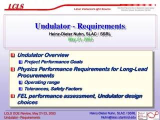
Undulator - Requirements Heinz-Dieter Nuhn, SLAC / SSRLMay 21, 2003 • Undulator Overview • Project Performance Goals • Physics Performance Requirements for Long-Lead Procurements • Operating range • Tolerances, Safety Factors • FEL performance assessment, Undulator design choices Heinz-Dieter Nuhn, SLAC / SSRL
Undulator Overview 421 187 3420 UNDULATOR 11055 mm Horizontal Steering Coil Vertical Steering Coil Beam Position Monitor X-Ray Diagnostics Quadrupoles Heinz-Dieter Nuhn, SLAC / SSRL
Nominal Undulator Design Undulator Type planar hybrid Magnet Material NdFeB Wiggle Plane horizontal Gap 6 mm Period Length 3 cm Peak On-Axis Field 1.32 T K 3.71 Segment Length 3.42 m Number of Segments 33 Segment Break Lengths 0.187-0.421 m Undulator Magnet Length 112.8 m Undulator Device Length (incl. Breaks) 121.1 m Undulator Filling Factor 93 % Heinz-Dieter Nuhn, SLAC / SSRL
Undulator Performance Requirements Heinz-Dieter Nuhn, SLAC / SSRL
Path Length Increase in Bumps Straightness Tolerance Tolerance from Path Length Change Tolerance from Overlap Heinz-Dieter Nuhn, SLAC / SSRL
Trajectory Straightness Tolerance Mean phase error per meter of undulator vs. BPM spacing, L, for a BPM resolution of <b2>1/2=1mm, and dipole field errors of (DB/Bo)rms = 0.1% (red), 0.05% (blue), and 0.025% (green). The optimum BPM spacing moves from 1.8 m at 0.10 % to 4.4 m at 0.025%. Points with error bars are a Monte Carlo computer calculation at 0.10 % used as a cross check (lu = 3 cm, lr = 1.5 Å, and gmc2=14.3 GeV) Pole Field Error can be Strongly reduced. P. Emma, SLAC, LCLS-TN-00-14 Heinz-Dieter Nuhn, SLAC / SSRL
Elegant Genesis Parmela space-charge compression, wakes, CSR, … SASE FEL with wakes 1.0 nC strong wakefields losses due to spon. rad. Charge deepsaturation Operation Space 0.2 nC Wavelength 1.5 Å 15 Å FEL Simulations Parameter Range Start-To-End Simulations: Lowering the charge reduces bunch length, current and emittance Heinz-Dieter Nuhn, SLAC / SSRL
Performance Limitations Spontaneous Radiation • Energy loss due to spontaneous radiation. Weak taper of undulator field to compensate change in resonance condition • Quantum fluctuation of hard X-rays increases energy spread. No compensation possible ! Spon. rad. FEL process FEL process Quantum fluctuation Heinz-Dieter Nuhn, SLAC / SSRL
PerformanceLimitations Undulator Wakefields Caused by • wall resistivity, • surface roughness, • changes in aperture. Resistive wall wakefields are the dominant contribution to the total wake potential. Larger undulator gap does not increase output power but the saturation length! Current Profile Wake Potential Without wakefields With wakefields Heinz-Dieter Nuhn, SLAC / SSRL
Beam Quality Issues • Slippage length, over which beam information is transported via the radiation field, is 500 nm at 1.5 Å wavelength. Many parts of the bunch amplify the spontaneous radiation independently of each other. • If magnitude of correlated energy spread is larger than the FEL bandwidth, the frequency spectrum is broader. • The matching of the projected phase space ellipse to the focusing lattice causes a mismatch and misalignment along the bunch. • Wakefields have a ‘local’ effect, resulting in a position-dependent change in energy, which cannot be compensated by tapering. Beam quality is better parameterized by slicedrather than projected values Heinz-Dieter Nuhn, SLAC / SSRL
General Performance The most critical parameter is the transverse emittance. A large emittance corresponds to a large spread in transverse and, thus, longitudinal velocity. The effective number of electrons, which are in resonance with the radiation field, is significantly reduced. The emittance effects dominate over the energy spread, which also causes a spread in longitudinal motion. 1.7 mm.mrad is the largest slice emittance, which allows saturation within the LCLS Undulator (120 m, including gaps between modules), assuming a local current of 3.4 kA. Heinz-Dieter Nuhn, SLAC / SSRL
Expected Performance • Start-end simulation using PARMELA-ELEGANT-GENESIS 1.3 • 4 cases (1nC and 0.2 nC at 1.5 Å and 15 Å) • Low charge cases are modeled in PARMELA after the GTF results and then imported into ELEGANT for the transport through the LCLS beam line. • The simulations includes: • Space charge in the gun • Emittance compensation • Wakefield and CSR effects • Optimized beam transport (Jitter) • Spontaneous Undulator Radiation All cases reach saturation Heinz-Dieter Nuhn, SLAC / SSRL
Impact of Wakefields Large wake amplitude due to spikes in the current profile at the beginning and end of the electron bunch. Stronger at 1.5 Å: Smaller bandwidth Longer accumulation Power reduction at undulator exit Expected Performance Heinz-Dieter Nuhn, SLAC / SSRL
Power Profile Expected Performance Profile similar for entire wavelength range. • Gaps in profile due to • Undulator wakes • Large emittance • Large energy spread Heinz-Dieter Nuhn, SLAC / SSRL
Workshop on Start-To-End Simulations Beam Dynamics Mini Workshop Future Light Sources Start-To-End Simulations for SASE FELs (S2E 2003) Chaired by John Galayda (SLAC) and Joerg Rossbach (DESY) Dates August 18 – 22, 2003 Location DESY-Zeuthen, Berlin, Germany Heinz-Dieter Nuhn, SLAC / SSRL
LCLS Working Point at Short Wavelength End Extendable Undulator Length Available Undulator Length 2.0 mm mrad 1.7 mm mrad 1.2 mm mrad Nominal Working Point Saturation predicted 30 m before undulator end Space for Undulator Extension Available if needed. Length of Dogleg 2 65.518 m Length of Extension Space 30.969 m Length of Undulator 121.045 m Heinz-Dieter Nuhn, SLAC / SSRL
Nominal Working Point LCLS Working Point at Long Wavelength End Strongly reduced requirements for electron beam parameters to achieve saturation before end of undulator. Heinz-Dieter Nuhn, SLAC / SSRL
LCLS Working Point Heinz-Dieter Nuhn, SLAC / SSRL
Undulator Gap Issues Vacuum Chamber Outside Diameter 5.6 – 6.0 mm Undulator Gap 6.0 – 6.4 mm • Tight vacuum chamber fit • prevents independent chamber support • does not allow for segment removal Heinz-Dieter Nuhn, SLAC / SSRL
LCLS Undulator Gap and Period Selection Proposed Undulator Length Safety Overhead Emittance Goal Emittance Achieved Heinz-Dieter Nuhn, SLAC / SSRL
Conclusions • Requirements for undulator long-lead procurements are well established • LCLS undulator performance requirements are well understood • Risks have been assessed and undulator specifications address the risks • … Heinz-Dieter Nuhn, SLAC / SSRL