Download

1 / 72
720 likes | 918 Views
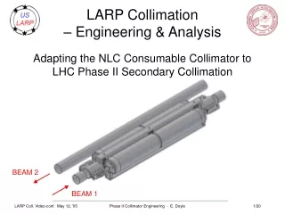
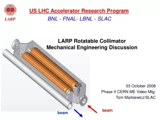
US LHC Accelerator Research Program. BNL - FNAL- LBNL - SLAC. LARP Rotatable Collimators for LHC Phase II Collimation. 26 October 2006 LARP Collaboration Meeting – Port Jefferson, NY Tom Markiewicz/SLAC Representing Eric Doyle, Lew Keller & Steve Lundgren. beam. beam.

E N D
US LHC Accelerator Research Program BNL - FNAL- LBNL - SLAC LARP Rotatable Collimators for LHC Phase II Collimation 26 October 2006 LARP Collaboration Meeting – Port Jefferson, NY Tom Markiewicz/SLAC Representing Eric Doyle, Lew Keller & Steve Lundgren
beam beam Collimator Design as of April 2006 • 136mm diameter x 950 mm long copper jaws (750 mm effective length + 2 x 100mm tapers) • Vacuum tank, jaw support mechanism and support base derived from CERN Phase I Rotatable Collimators - T. Markiewicz
Collimator Design as of April 2006 NLC Jaw Ratchet Mechanism assumed 25mm thick annular (hollow core) copper jaw backed by continuous helical cooling tube Sheet Metal formed RF transition CERN PHASE I JAW POSITIONING MECHANISM – USE IF POSSIBLE EXTERNAL COIL PERMITS 1 REV OF JAW Rotatable Collimators - T. Markiewicz
Adjustable central aperture-defining stop and leaf spring support required to prevent jaws from deforming 1200um into beam • Leaf springs allow jaw end motion up to 1mm away from beam. Must allow: • Thermal motion while minimizing gravity-deflection • Axial expansion • Stop prevents thermal bowing of jaws from intruding on minimum gap. Deal with: • Residual swelling into beam • External vertical actuator and bellows that also has +/- 5mm transverse float • Mid-jaw recess • Forces possibly unbalanced front vs. back Rotatable Collimators - T. Markiewicz
Spring loaded fingers ground two jaws through range of motion Rigid round-square transition Jaw support & gap adjustment borrowed from CERN RF Contact Scheme Blessed by CERN Impedance Police Rotatable Collimators - T. Markiewicz
Baseline Jaw Performance Exceeds spec, or other possible problem as noted Baseline: hollow Cu, 25mm wall, helical cooling - 5cm pitch Exceeds 200 Max Cu temp Possible boiling Exceeds 42 max water return temp Exceeds Allowed Deflections All temperature simulations based on 20C supply. For CERN 27C supply add 7 to all temperature results. CERN max water return temp 42C Rotatable Collimators - T. Markiewicz
Technical Review of Baseline 12-2005 • Do not ‘cut metal’ until jaw support, stop and rotation scheme developed • Increase engineering effort • Response • Full time engineer (Steve Lundgren) & full time designer hired April 2006 • Doyle, Keller, & Markiewicz continue on part time basis • Result • New jaw design developed which eliminates central stop & flexible springs • New concept for winding the cooling coil which eliminates the 4 loops per end and permits longer jaw and better RF-compliant jaw support • New scheme for rotating after beam abort damages surface • Test pieces constructed & examined • BUT… • Still do not have tested full length jaw or complete RC1 prototype Rotatable Collimators - T. Markiewicz
Progress since April 2006 Meeting • Design & Calculation • Improved and much more complete design • ANSYS calculations to simulate performance of new design • ANSYS calculations to start to look at permanent deformation in case of accidental beam abort • FLUKA model improvements to understand heating/cooling in more elements (shaft, bearings, …) of the collimator • Fabrication • Fab, brazing & dissection of short (15cm) section of jaw: • cooling coil to mandrel and of coil/mandrel assembly to jaw • Fabrication of short aluminum mandrel to practice coil winding & development of coil winding tooling • Fabrication of 2nd short (20cm) copper mandrel and jaw pieces • test braze techniques required for longer jaw pieces Rotatable Collimators - T. Markiewicz
Advances since RC1 Baseline more cooling solid core Rotatable Collimators - T. Markiewicz
New Idea to Eliminate Central Stop Jaw-Hub-Shaft shaft hub jaw • Hub located, in Z, near peak temperature location, which lowers peak temperature, reducing gradient and bending. • Max deflection toward beam reduced if the shaft deflection can be minimized • Both ends of jaw deflect away from beam. (Note: swelling component of deflection is not corrected.) • Cooling coils embedded in I.D. of outer cylinder. Rotatable Collimators - T. Markiewicz
Evaluate jaw-hub-shaft for 950mm jawsw/ 22.5mm deep cooling tubes with hollow Moly shaftversus 750mm jaw baseline & 750mm jaw solid copper shaft refined baseline SS 1hr beam Transient 10sec @12min beam New Baseline • Notes: • Deflection means deviation from straight (um). • Eff length is length of jaw (m) deflected <100 um compared to maximum deflection point. • Deflection is combination of swelling and shaft bending • Shaft static deflection due to gravity = 68um • 7 s min allowable aperture achieved by setting jaws of first collimator at 8.5 s. Rotatable Collimators - T. Markiewicz
Restrain each tube on centerline of bearing 136mm dia 200mm First Concept to Eliminate 4-Loop Coils at Ends to allow increased jaw length and realistic jaw holder that is “plug&play” replacement for Phase I jaw Lundren Model of Coil Winding Test piece 200mm long x 86mm diameter Annealed pre-bent cooling coil and dead recon winding to put U-Bend at exact midpoint of mandrel Rotatable Collimators - T. Markiewicz
Summary of New Baseline Configurationon 1 Sept 2006 ( slight mods since) • Jaw consists of a tubular jaw with embedded cooling tubes, a concentric inner shaft joined by a hub located at mid-jaw • Major thermal jaw deformation away from beam • No centrally located aperture-defining stop • No spring-mounted jaw end supports • Jaw is a 950mm long faceted, 20 sided polygon of Glidcop • Shorter end taper: 15mm L at 15o (effective length 920mm) (now slightly shorter) • Cooling tube is square 10mm Cu w/ 7mm square aperture at depth = 24.5 mm • Jaw is supported in holder • jaw rotate-able within holder • jaw/holder is plug-in replacement for Phase I jaw • Nominal aperture setting of FIRST COLLIMATOR as low as 8.5 s • Results in minimum aperture > 7s in transient 12 min beam lifetime event (interactions with first carbon primary TCPV) • Absorbed power relatively insensitive to aperture: for 950mm long jaw p=12.7kW (7s), p=12.4kW (8.23s) • Auto-retraction not available for some jaw orientations • Jaw rotation by means of worm gear/ratchet mechanism “Geneva Mechanism” Rotatable Collimators - T. Markiewicz
Power Absorption in BOTH Copper Jaws of First Secondary Collimator TCSM.A6L7 Lew Keller Rotatable Collimators - T. Markiewicz
Collimator Inefficiency when the TCSM.A6L7 collimator only is opened from 7 to 8 or 8.5 sigma for each beam and for each primary collimator orientation Chiara Bracco / CERN Rotatable Collimators - T. Markiewicz
Contribution to inefficiency from each of several collimators as 1st secondary is opened from 7 to 8 sigma Chiara Bracco / CERN Rotatable Collimators - T. Markiewicz
Steps on Path to a Thermal Test of a Full Length Cooled Jaw: #1 Test Pieces • Braze Test #1 • Wind any available 10mm x 10mm tubing on convenient sized and available copper stock for mandrel and jaws • Develop and document braze procedures • Section for braze inspection, document results • Coil winding Procedure and hardware • Develop procedure and tooling to wind available tubing on short 200mm length Aluminum mandrel • Test 3-axis CNC milling procedure required to machine U-bend in cooling pattern • Braze Test #2 • Machine short 200mm copper mandrel • Wind annealed available tubing on copper mandrel and stake in place to hold • Braze tubing to mandrel • Machine OD and add groove to hold braze wire • Machine 4 quarter 200mm jaws • Braze with wire & foil • Section for braze inspection, document results Rotatable Collimators - T. Markiewicz
Cooling Tube Jaw Center Mandrel ~70 mm dia ~100 mm dia ~100 mm BrazeTest #1 Rotatable Collimators - T. Markiewicz
Aluminum Mandrel for Coil Winding Test and to test 3-axis CNC Mill before cutting 200mm and 950mm Copper Mandrels Cooling Tube aligner 200mm Rotatable Collimators - T. Markiewicz
Test Bends on Square Hollow Copper Tubing • Preliminary bends just to get some experience Initial test bend of “Half Turn” wound by hand Rotatable Collimators - T. Markiewicz
Attempts to Use Tooling for Bending • Lathe • Magnet Coil Winding Instrument Rotatable Collimators - T. Markiewicz
Development of Winding Tooling Aluminum Mandrel with Coil Wound Roller-Type Vise-Type Test Winding the 200mm Copper Mandrel Rotatable Collimators - T. Markiewicz
Fabrication of Quarter Jaws for 2nd Braze Test Rotatable Collimators - T. Markiewicz
Final Wind of 200mm Copper Mandrel Rotatable Collimators - T. Markiewicz
Update Cooling Coil Wind Concept Based on 200mm Wind Tests • Shifting the u-bend from the midpoint of the Mandrel to near the downstream end gives the following benefits: • The groove in the u-bend area can be eliminated reducing the need for precise initial bend locations. • The u-bend can be made larger in diameter to reduce the internal distortions in the cooling channel and improve water flow. • The groove and relief can be machined on a lathe rather than on a CNC milling machine reducing the overall cost. • Result • Mandrel has a groove the appropriate width and depth for the conductor and goes 42.5 turns in the same direction. • Mandrel has one 80mm wide “groove” at downstream end to accommodate the u-bend and a enough conductor wrap around about 1 turn (provides a generous allowance for errors in machining and bending locations). • U-bend can be 20 to 30mm diameter not only 10mm Lundgren Rotatable Collimators - T. Markiewicz
Model showing Coil wound on Mandrel with U-Bend at downstream end • Note: Braze Test #3 will probably need to be added to step #1 • Fab 2nd 200mm mandrel on lathe • Test wind coil with downstream U-Bend • Under discussion: use 8 quarter round jaw sections to make sure butt brazes pose no problem (as promised) Rotatable Collimators - T. Markiewicz
Steps on Path to a Thermal Test of a Full Length Cooled Jaw #2 Manufacture Full Length Jaw • Machine 930mm mandrel with new winding pattern • Mandrel had been released for fabrication with requested due date 10/27/06 • Drawings for full length mandrel modified to put loop at end and resubmitted • Acquire CERN-compliant (Nickel alloyed) copper tubing from Finland • Build tooling using roller concept for full length jaw • Shape & anneal tubing • Wind tubing to mandrel • Machine OD and add groove to hold braze wire • Machine (wire EDM) at least 8 full half length (465mm) quarter jaws from copper (NB: Final jaws will be Glidcop) • Released to SLAC shops for fabrication on 1 OCT 2006, • Original promise date 11/08/06 • Cost estimates are very high and we are examining issues involved in designing shorter pieces fabricated by other means • Braze jaws to mandrel assembly • Design & order shaft in MOLYBDENUM • Order has been placed with vendor: promise date 11/28/06 • Braze shaft to jaw assembly • Machine 20 facets on jaw face • Machine features required to interface resistive heater packages Rotatable Collimators - T. Markiewicz
ANSYS Model of Jaw-hub-shaft with hollow Mo shaft Simple supports at both shaft ends Deflection Hollow Mo Shaft Hub region - centered Temp Glidcop Jaw Rotatable Collimators - T. Markiewicz
Comparison of Hollow Mo shaft and Solid Copper Shaft to same FLUKA secondaries: Improved deflections Rotatable Collimators - T. Markiewicz
Molybdenum Shaft Details 1mm raised shoulder (Hub) at center Relief on O.D is for stiffening sleeve and worm gear mounting Slots for tubing extend past bearing and are 180 deg offset Relief on I.D. is for roller bearing Rotatable Collimators - T. Markiewicz
Single Jaw Thermal Test Hardware • Jaw Sections ~450 mm long Jaw sections are manufactured as quarter cylinders for fabrication accuracy and ease of braze assembly Only 4 or 5 flats are planned for the test and for measurement purposes Rotatable Collimators - T. Markiewicz
Steps on Path to a Thermal Test of a Full Length Cooled Jaw #3: Test Fixture • Specify details of test stand • Make design drawings • Fabricate Rotatable Collimators - T. Markiewicz
Steps on Path to a Thermal Test of a Full Length Cooled Jaw #4: Test Lab Preparation • Clean space with gantry access • Basic equipment: Granite table, racks, hand tools • Power supplies to drive heaters • Chiller & plumbed (?) LCW to cool jaw • 480V wiring for heater power supplies • required engineering review, safety review, and multiple bids (?!) • 23 Nov 2006 promise date • Acquire Heaters • 5kW resistive heaters available on short notice from OMEGA • PC & Labview • Rudimentary software tests only • National Instruments DAQ with ADCs • Data Acquisition and Control Module • 32-Channel Isothermal Terminal Block • 32-Channel Amplifier • Thermocouples (?) • Capacitive Sensors (?) • Vacuum or Nitrogen (?) • Safety Authorization (!!!) Collimator Assembly & Test Area in SLAC Bldg.33 Rotatable Collimators - T. Markiewicz
Equipping of Clean Collimator Test Area Granite surface plate Adjacent 16.5 kW Chiller Heater Power Supplies staged for installation in rack Instrumentation rack and computer workstation Rotatable Collimators - T. Markiewicz
Beginnings of System Schematic for Single Jaw Thermal Test Hardware Test Lab Setup Block Diagram Bldg Power fuse Heater #1 Controller Jaw Heater #1 fuse 100 Amp Tap Over Temperature Control fuse Heater #2 Controller Jaw Heater #2 fuse PC with LabView Software Jaw Internal Cooling Line Capacitec Signal Amplifier Jaw deflection sensors Chiller DAC & Signal Processor Jaw thermocouples Bldg Power LCW Water (Supply) LCW Water (Return) Rotatable Collimators - T. Markiewicz
Steps on Path to RC1 • Successful thermal performance of first full length jaw • Complete design of RC1 support, rotation & RF features • Layouts, calculations and models of two Jaw mounting methods as well as a rotation scheme have been explored…. • Detail drawings of the preferred Jaw mounting method and rotation mechanism are in work. • A working model is planned to verify the rotation scheme with respect to Jaw face position accuracy. • Acquisition, Fabrication & Assembly cycle of the support, rotation & pieces • Fit-up and initial tests on 1st full length jaw • Complete fabrication of second jaw (Glidcop?, Moly??) with full support assembly • Remodeling of CERN parts for interface to US parts • Models and assemblies of the various Collimator Mounting Stands are complete • An enlarged vacuum tank has been modeled and some CERN support stand modifications have been identified • No fabrication drawings have been done as yet • Acquisition of Phase I support & mover assemblies • Given delivery difficulties of CERN Phase I this has dropped off CERCA/AREAV and CERN event horizon despite promise 1 May 2006 that SLAC quote was “in the mail” Rotatable Collimators - T. Markiewicz
August 2006 “Plug & Play” Model of Jaw Mounts Lundgren Rotatable Collimators - T. Markiewicz
August 2006 Jaw mounting details • Draws on features from CERN Phase 1 Collimator Lundgren Top and Bottom RF springs (not shown) are identical To CERN part Positioning and Guiding Plates are similar to CERN Design Note 20-sided faceted face: CERNContact RF Assy can be used Press here to activate 2 leaf springs producing linear motion to rotate a worm/ratchet shaft Modified CERN Pivot Tensioning Plate Rotatable Collimators - T. Markiewicz
August 2006 Ratchet, Worm and Worm Gear • Shaft and Jaw mount details not shown for clarity 100 Tooth Worm Gear (mounts to shaft) Single turn Worm 20 Tooth ratchet Bearing 2X Lundgren Rotatable Collimators - T. Markiewicz
October 2006 Design Model Replaces Worm Gear with “Geneva Mechanism” for Jaw Rotation and Replaces Needle Bearings with Universal Joint and Angular Contact Bearings and Incorporates Cooling for Support Pieces • A Geneva Mechanism is the key factor in indexing the Jaw. • Prevents possible over-run of ratchet. • Eliminates step count as determining factor in exact facet positioning. • Universal joints connect Jaw ends to angular contact bearing sets. • The stainless steel diaphragm “u-joint” meets required torque, Jaw/shaft sag and end-to-end “slew” offset spec of =/-1.5 mm. • ANSYS calculations performed to verify diaphragm thickness & dia. • Built-in hard stops prevent damage from potential high accelerations during handling and transport. • Maximum stress on diaphragm is 1/2 yield strength of the stainless steel. Lundgren Rotatable Collimators - T. Markiewicz
Universal Joint required motions • Thermal Expansion of molybdenum Shaft of 0.290mm (transient) causes each diaphragm to distort by 0.145mm. • Shaft sag causes an in plane rotation of the Shaft ends of 0.00025 radians causing an equal distortion of the diaphragm. • Transverse displacement one of the ends of the Shaft relative to the other by +/- 1.5mm causes an angular distortion of 0.0015 radians in the diaphragm. • Worst case is for a Vertical Collimator with maximum “slew” of 0.0015 radians added to the sag component of 0.00025 radians • for a total of 0.00175 radians of bending of the diaphragm. Lundgren Rotatable Collimators - T. Markiewicz
Jaw Mount with Geneva Mechanism Lundgren Geneva Driver Wheel (on ratchet shaft) Geneva Driven Wheel (on Worm shaft) 0.5mm thick diaphragm 100 Tooth Worm Gear Rotatable Collimators - T. Markiewicz
Jaw Mount section view with safety stop Lundgren Hard Stop Angular contact bearings 0.5mm thick Diaphragm Shaft mounts here Rotatable Collimators - T. Markiewicz
Upstream end vertical section Lundgren Jaw Geneva Mechanism Worm Gear Shaft Water Cooling Channel U-Joint Axle Support Bearings Rotatable Collimators - T. Markiewicz
Upstream end horizontal section • Support to Support 1000mm Overall length 930mm Facet length ~905mm Lundgren Rotatable Collimators - T. Markiewicz
Upstream end with actuator and cooling lines Lundgren Rotatable Collimators - T. Markiewicz
Upstream End looking Downstream Lundgren Flexible Vane supports each end of Image Current Plate Rotatable Collimators - T. Markiewicz
Image Current Plate Lundgren Rotatable Collimators - T. Markiewicz
Jaw-Hub-Shaft Key Dimensions Rotatable Collimators - T. Markiewicz
Copper cylinder + cooling loops: R = 3.3 – 6.8 CM, Z = 95 CM Molybdenum shaft: R = 2.2 -3.2 cm ceramic bearing bearing axle Alum. Alum. beam axis image current block Extension of SLAC Simple FLUKA Model to include cylinder Copper jaws, Hollow Moly Shaft, Ceramic bearings, Shaft axel, and support blocks for TCSM-A6L7 Lew Keller Rotatable Collimators - T. Markiewicz