Download
1 / 12
120 likes | 387 Views
National Institute for Aerospace Researches “Elie Carafoli” - INCAS SA, Bucharest 220, Iuliu Maniu, Sect 6, Bucharest, Phone:004.021.434.00.83, Fax:004.021.434.00.82 web: www.incas.ro, e-mail: incas@aero.incas.ro. INCAS.

E N D
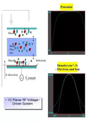
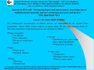
National Institute for Aerospace Researches “Elie Carafoli” - INCAS SA, Bucharest 220, Iuliu Maniu, Sect 6, Bucharest, Phone:004.021.434.00.83, Fax:004.021.434.00.82 web: www.incas.ro, e-mail: incas@aero.incas.ro INCAS Interest in FP 6 call: 'Nanotechnologies and nanosciences, knowledge-based multifunctional materials and new production processes and devices ‘ – FP6-2004-NMP-TI-4 3.4.2.2.1. PLASMA PROCESSING* The fundamental characteristics of plasma process are represented by the assured flame temperature , about 15000Celsius degrees, jet speed about 300 m/s, layer porosity about 2%. The main parameters of the plasma process are sketched as follows: • Plasma parameters: • Air dilution • Gas composition • Plasma jet temperature • Speed • Powder: • Distribution,size, grain shape • Spray speed distribution • Staying time in plasma • Flame: • Flame speed • Spraying distance • Under layer • Temperature • Residual tension control • Particle impact speed • Nozzle: • Flow gas • Powder flow * In connection with 3.4.2.2. TECHNOLOGIES ASSOCIATED WITH THE PRODUCTION, TRANSFORMATION AND PROCESSING OF KNOWLEDGE-BASED MULTIFUNCTIONAL MATERIALS
Industry Function of coatings 1 2 3 4 5 6 7 8 9 10 11 Chemical Power Space and aeronautical Nuclear Medicine Metallurgy Materials technology Table 1 The potential application of the plasma coatings • - high potential • - industrial application • or in progress of • introducing • - in progress of development • Without symbol – unexplored potential 1 – anticorrosive protections; 2 – anti wear protections; 3 – electronic proprieties; 4 – radiation; 5 – chemical/biological proprieties; 6 – ended form; 7 – restore; 8 – powder processing; 9 – sensitive composite; 10 – unstable materials; 11 – amorphous coatings trough solidification
The process limits are specially determined by the reduced adherence between metal support and • bonding layers, high porosity and partial oxidation of the particles. • Fundamental problems to be solved in our opinion by the research in the field are represents by the: • Plasma generator power increase; • Powder flow speed increase; • Comparable study of the condition by air pressure environment about layers porosity, structure modification , deposition part; • Realisation for management of the technological process, especial for ceramic layers of a relax structure with deliberate accomplished porosity and micro cracks; • Computerised metallography and electronic microscopy investigations regarding the interface aspects, support - adherence layer - external layers and dynamic of the modifications induced by different mechanic and thermal stresses. Withintheconsortium, in connection with this theme, INCASis able to participate in the activities associated to the last two paragraphs. Fig. 1 Plasma jet installation
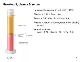
National Institute for Aerospace Researches “Elie Carafoli” - INCAS SA, Bucharest 220, Iuliu Maniu, Sect 6, Bucharest, Phone:004.021.434.00.83, Fax:004.021.434.00.82 web: www.incas.ro, e-mail: incas@aero.incas.ro INCAS 3.4.2.2.3. MULTIFUNCTIONAL CERAMIC THIN FILMS WITH RADICALLY NEW PROPERTIES INCAS have the experience to achievesome duplex, triplex layers, FGM - functionally graded materials, ceramics for industrial proposed especial for “hot parts” of turbojet, for some metallurgy parts, power industry, etc. The aimed parts are stressed at erosive, corrosive wear, thermal shock, sliding friction, which can work simultaneously at high values. The ceramic layersunanimous utilized, generally partial stabilized zirconia base, have as main servitude, the major difference between thermal expansion coefficients values ofceramic layers and metallic support during thermal shock and associated induced internal stressed. To decrease the thermal shock effect on the ceramic layers, multilayered structures, FGM, etc. are utilized. Each intermediate layer composition is graded between external layers (internal and external). A progress in this domain, is represented by the recent experimental studies performed by Lewis Research Center, Cleveland, Ohio, for plasma sprayed coatings. An improved bond coat, incorporating metallic or ceramic and cermets layers has been demonstrated to increase the thermal fatigue life of a plasma sprayed TBC by a factor of two or more. Utilizing this system, the second layer of the bond coat incorporates a fine dispersion of a particulate second phase in a MeCrAlY matrix. The second phase is required to have a coefficient of thermal expansion as low as possible or preferable lower than yttrium zirconium layer and it must be stable up to intended temperature, chemically inert with respect to the MeCrAlY matrix and must be chemically compatible with the thermal grown alumina scale.
INCAS has in progress evaluation experiments of the triplex layer type MeCrAlY/MeCrAlY 90% + Al2O3 10%/ZrO2. Y2O3 obtained by plasma spray technology . The achievement of some thin layers impose the CVD, PVD, Sputtering, etc. technologies . Fig. 2 Ceramic and bonding layers, SEM imagine Fig. 3 Zr associate distribution Within the consortium, in this direction, INCAS is able to participate especially in the achievement of some multifunctional layers , thermal shock stressed .
National Institute for Aerospace Researches “Elie Carafoli” - INCAS SA, Bucharest 220, Iuliu Maniu, Sect 6, Bucharest, Phone:004.021.434.00.83, Fax:004.021.434.00.82 web: www.incas.ro, e-mail: incas@aero.incas.ro INCAS Quick thermal shock test installation for multifunctional ceramic coatings • Protection layers and especial ceramics have main servitude lower resistance at thermal shock. • For aeronautical application, rockets, metallurgical, power industries, is important the behavior of • this coatings in limited functional conditions - with additionally requests. • Thermal shock classical installation mentioned in literature have heating • cooling cycle with substantial low speed than extreme functional conditions. In the same • context are not testing methods in extreme condition, unanimous accepted. • The main characteristics of the proposed thermal shock installation: • testing sample dimensions-rectangle LxWxH {mm} - 25x25x2;or circular 25x1÷2 mm • the test specimen materials: metals, alloys, composite materials, ceramic materials, coatings • (enamel, multilayered, TBC, FGM, etc.) • maximum testing temperature: +1400 degrees Celsius • heating time from the environment temperature till the testing temperature:15÷150 sec • cooling time from the testing temperature till the environment temperature:15 ÷250 sec • temperature speed measurement : 150 ms • sample view during the test • temperatures measurement during all the time test • samples photo in the heating and cooling areas • samples lighting in the heating and cooling areas • manual cycle • automatic cycle
work parameters registration: • - environment temperature • - oven temperature • - sample temperature • - heating time • - cooling time • - cycle working time • - graphic and table display of samples temperatures against time and position during the test • This installation is absolutely necessary, in our opinion, for testing and selection • of the ceramic layers in extreme functional condition, for industrial applications. • INCAS is able to conceive, design and achieve (in cooperation with European partners) quick thermal shock installation for ceramic layers by FGM type.
National Institute for Aerospace Researches “Elie Carafoli” - INCAS SA, Bucharest 220, Iuliu Maniu, Sect 6, Bucharest, Phone:004.021.434.00.83, Fax:004.021.434.00.82 web: www.incas.ro, e-mail: incas@aero.incas.ro INCAS 3.4.2.3.1.1. Nanocomposites epoxy-Montmorillonite* Nanocomposites are a new class of advanced, nanometer-scale multiphase polymer composites that often display many enhanced physical properties: strength, hardness, thermal and viscoelastic properties. Nanocomposites are synthesized by dispersing expholiated clays, nanometer particle and aggregates into a polymer matrix (epoxy) or by infiltrating epoxy into the interlayer structure of layered silicates. INCAS in cooperation with ICECHIM Bucharest develop researches regarding nanocomposites epoxy- Montmorillonite (aluminum hydrate silicate), via second way. In the first stage some samples of epoxy resin as such and epoxy-10% Montmorillonite (weight) are performed. The mechanical testing results up to date are synthesized in table 2. Table no. 2 Epoxy resin characteristics with and without Montmorillonite It is to notice the significant effect of the Montmorillonite addition upon the elasticity modulus. The researches will be continued with complementary studies regard nanocomposites-epoxy-glass fiber, nano epoxy-fibers composites and maybe nano epoxy-carbonnanotube, incorporated.. * In connection with3.4.2.3. ENGINEERING SUPPORT FOR MATERIALS DEVELOPMENT, 3.4.2.3.1. MATERIALS BY DESIGN: MULTIFUNCTIONAL ORGANIC MATERIALS
National Institute for Aerospace Researches “Elie Carafoli” - INCAS SA, Bucharest 220, Iuliu Maniu, Sect 6, Bucharest, Phone:004.021.434.00.83, Fax:004.021.434.00.82 web: www.incas.ro, e-mail: incas@aero.incas.ro INCAS 3.4.3.1.1.1. Carbon – carbon composites nano-ceramic matrix* Carbon fiber and carbon-carbon was first developed for aerospace technology (component in missiles, reentry vehicles, in space shuttles as structural parts and as brake lining and brake disc material for civil and military aircraft). Materials and Tribology Department of INCAS realized performing carbon fiber (PAN precursor) and carbon-carbon composites, phenolic matrix. In fig. 4 and Fig. 5 the Debyegram of PAN precursor and thermooxidate PAN are presented. Intensity diminution of peak diffraction points out adequate PAN stabilization. Fig. 4 PAN Debyegram Fig. 5 Debyegram of the thermooxidate PAN * 3.4.3.1. DEVELOPMENT OF NEW PROCESSES AND FLEXIBLE, INTELLIGENT MANUFACTURING SYSTEMS 3.4.3.1.1. NEW PRODUCTION TECHNOLOGIES FOR NEW MICRO-DEVICES USING ULTRA PRECISION ENGINEERING TECHNIQUES
Some characteristics of FC obtained are synthesized in table 3. Table 3 Characteristics of FC
In fig. 8 and fig. 9 are point out the effects of thermal treatment upon density and mechanical characteristics of the C-C composites. • Recently researches report on C-C composites and nano C-C composites as brake materials. • The main features of C-C as friction materials for aircraft brakes are: • a great ablation heat (20.000 Kcal/Kg) • specific weight 1,7 ÷ 1,9 Kg/dm3 • friction coefficient 0,3 • dimensional stability at high temperatures (small dilatation coefficient, max 2x10⁻⁶ v.s.10-5 for steel)
For concordance in tribological and antioxidant properties of C-C composites distinct solutions was • developed: • FC - fiber (unidirectional 2D tissue, chopped, felt preform) and phenolic matrix with 25% CSi (reported • to phenolic resin) • Nanocomposites C-C ceramic matrix via so called LSI (Liquid Silicon Infiltration). • The sol gel SiO2 (50% weight reported to phenolic resin) infiltrated in a C-C by thermal treatment • at 1600°C generate ceramic matrix (CSi). The results of tribological testing are presented in table no 5: Table 5 Friction coefficients for C-C composites In the future INCAS- Material and Tribology Laboratory aims to achieve carbon fiber composites ceramic matrix, via nanosilicium carbide-mesophase, or to use polymeric precursor (policarbosilane) for CSi matrix.