Download

1 / 45
470 likes | 767 Views
Silicon detectors in HEP. Enver Alagoz ACCTR Meeting 18 August 2012. Introduction to silicon. S emiconductor material Used for radiation detection/imaging in Particle and nuclear physics experiments Space and ground-based telescopes Medical applications Industrial applications …

E N D
Silicon detectors in HEP EnverAlagoz ACCTR Meeting 18 August 2012
Introduction to silicon • Semiconductor material • Used for radiation detection/imaging in • Particle and nuclear physics experiments • Space and ground-based telescopes • Medical applications • Industrial applications • … • Interacts with radiation • Radiation creates charge carriers • Electric field drifts carriers toward readout electronics • Signal integrated in frond-end electronics • Digitize integrated signal • Readout and store digital signal
Particle reconstruction in time Pre-silicon era • Why detectors change • Interested in rare events • in very high energies • with very small uncertainties • with very high background • Need high precision • Very high granularity • low material budget • High particle collision rates • High speed electronics • Good background tolerance • Long term reliability • Radiation hardness 1970s Si + gaseous tracking 1990s Si tracking+vertex+calorimetry 2010s time
Gaseous vs silicon detectors • In silicon detector • No multiplication signal amplification needed • Optimum thickness to minimize multiple scattering
Vertex reconstruction Outer Si layer Outgoing particle Inner Si layer R1 R2 Impact parameter Primary vertex b IP If both layers have same spatial resolution (σ)
CMS pixel detector Barrel Pixel Forward Pixel
Silicon detectors in HEP • In HEP experiment • Vertex reconstruction • Fast detection and position resolution • Experiments with silicon detector E. Do Coutoe Silva, Vertex 2000, Sept 10-15, National Lakeshore, MI, USA
Why silicon? • 2nd most abundant element in Earth (28% by mass) • Easy to process and purify to 0.001 ppb • Natural SiO2 as insulation during fabrication • Found in form of silicate minerals and SO2 (silica – sand) • Discovered in 1824 by Swedish chemist J.J. Berzelius • Commercially utilized since 1824 Silicon crystal Silicon powder Spectral lines of Silicon
Basic properties – Band gap Insulator Semiconductor Conductor Conduction band Conduction band Conduction band electrons Eg~ 6 eV Eg~ 1.12 eV overlap holes Valanceband Valance band Valance band
Basic properties • Very pure material • Charge carriers are created by • thermal, optical, and other excitations or ionization • Four valance electrons (covalent bonds) • Silicon (Si) and Germanium (Ge) are common • Doped with extrinsic semiconductors • N-type: excess electrons (e- donor), i.e. P, As etc. • P-type: excess holes (e- acceptor), i.e. Al, B, Ga, etc.
Silicon PN-junction • Silicon detector are in basic form of PN-junction N-doped silicon P-doped silicon Conduction band Conduction band EC N-type: Phosphorus P-type: Boron Eg: Band gap (1.12 eV) EF Eg EF - + Valance band Valance band EV Excess hole Excess electron Si Si Si Si Si Si Si Si Si Si Si Acceptor impurity Si Donor impurity Si Si Si Si Si Si
Silicon pn-junction formation x=0 P-type neutral N-type neutral NA ND NA: # of acceptor impurities ND: # of donor impurities N,P Carrier concentration P N NA ND x Charge density ρ(x) eND x Electric field eNA E(x) x Φ(x) Coulomb potential x dP Depletion zone dn
PN-junction bias schemes WF WE N P N P E E _ + VF V = 0 WF : depletion width at forward bias WR : depletion width at reverse bias WE : depletion width in equilibrium WF < WE < WR WR N P E Reverse bias scheme is used for silicon detectors in HEP _ + VR
A real life case • Larger active area provided by n(p)-type subtstrate Depletion with n+ Resistivity depleted zone _ depletion p-type substrate t (thickness) VR Depletion voltage + E undepleted zone p+ Effective doping concentration
PN-junction current WF Current N P Forward current _ + Vbreakdown VF Voltage Reverse current (leakage) WR N P IPNα T3/2 exp[-Eg/2kBT] Avalanche current _ + VR
Leakage current Currentα T3/2 exp[-Eg/2kBT]
Breakdown voltage • Extracted from capacitance measurements W = t VFD
Charge collection • Carriers are drifted under the electric field μe- = 1500 cm2/Vs μh = 450 cm2/Vs • Total drift time for a carrier created at depth x VB = applied voltage VFD = full depletion voltage d = detector thickness • Maximum drift time (VB >> VFD) • For d = 300 μm
Radiation detection Ionization energy loss: • Ionization loss follows Landau statistics • Average energy loss is 390 eV/μm of Si • Average charge is 108 e-h/μm of Si • Most probable charge 80 e-h/μm of Si • 24 ke in 300 μm thick Si Most ionizing particle = Landau MP
Signal-to-Noise (S/N) • Signal is Landau, noise is Gaussian Most probable signal S/N = Noise Landau+Gaussian fit • Ionization energy loss follows • Landau statistics • Random electronic noise centered • at zero is Gaussian
Charge vs applied bias • Collected charge increases until full depletion is reached n+ _ depleted zone 300 um thick Silicon detector depletion t (thickness) VR + E undepletedzone p+
Silicon wafer fabrication • Hyper-pure polysilicon chunks • Melt and add impurity to make • n-type (P) or p-type (B) • Pour into a mold to make a • polysilicon cylinder • Melt onto a mono-crystal silicon • seed by means of RF power • Seed and melted polysilicon • rotations are opposite to grow a • round shape mono-crystal ingot • Employ a grindwheel to form the • ingot into a desirable diameters • Cut ingot into wafers by means • multi-wire-sawing • Lapping to flatten wafers • Chemical etching to smoothen • wafers • Edge rounding for wafer robustness
Device processing SiO2 Boron implantation (p+) UV light n-Si mask 800-1200 °C Phosphor implantation (n+) 600 °C etching SiO2 p+ p+ n-Si n+ Photo-resist layer metal metal p+ p+ n-Si n+ metal 1D silicon strip detector
Principle of operation n+ - - - - - - - - - + + + + + + + + + substrate E 1 4 3 2 • Preamplifier: amplifying small sensor signal • Pulse shaper: improving signal-to-noise ratio by filtering signal and attenuating electronic noise • Analog-to-Digital Converter (ADC) • Buffer: Store data • Front-end electronics add noise to signal (smearing). Low noise readout is essential p+
A silicon strip detector Readout electronics Strip sensor Wire bond (SEM image) Wire bond mechanism Wire bonds
Position resolution particle track pitch Pad sensor n+ particle track • Charge interpolation improves spatial resolution pitch n+ n+ E e- Segmented sensor E p+ p+
Position resolution Charge interpolated spatial resolution Binary spatial resolution
Silicon drift detector (SSD) ALICE SSD module
Pixel detector CMS BPIX module CMS barrel pixel detector
Detector topology Marco Battaglia Marco Battaglia, EDIT 2012, Silicon Track, February 2012
Radiation damage Recoil after 1 MeV neutron collision • Radiation induced damages • cause severe signal losses across • sensor thickness • Signal loss can be covered partially • by increasing high voltage • But high voltage • degrades the position resolution
Radiation damage effects • Leakage current increases ΔI = αΦ V • ΔI change in current in volume V • α is damage constant • Φ is time-integrated radiation flux • Depletion voltage increases VFD = q|Neff|d2 /2εε0 • Neff = |Ndonor-Nacceptor| • εε0 permittivity • d is sensor thickness • Charge collection degrades • Position resolution degrades
p+ n+ 50µm ionizing particle n+ depletion e 300µm p-type h p+ depletion p-type Radiation harder approaches – 3D • p+ and n+ electrodes are arrays of columns that penetrate into the bulk • Lateral depletion • Charge collection is sideways • Superior radiation hardness due to smaller electrode spacing: • - smaller carrier drift distance • - faster charge collection • - less carrier trapping • - lower depletion voltage • Higher noise • Complex, non-standard processing SEM picture of 3D electrodes PLANAR: 3D:
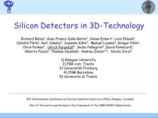
Radiation harder approaches – 3D 4E Configuration 2E Configuration n+ (readout) p+ (bias) SINTEF 3D (200 μm thick) Single-side etching 100 μm 150 μm 1E Configuration FBK 3D (200 μm thick) CNM 3D (200 μm thick) Double-side etching Double-side etching
References • Sze, Physics of semiconductor devices, 2nd Edition • HelmuthSpieler, Semiconductor Detector Systems • Olaf Steinkamp, Experimental Methods of Particle Physics, 2011 • EnverAlagoz, Simulation and beam test measurements of the CMS pixel detector, PhD Thesis, 2009 • Daniela Bortoletto, An introduction to semiconductor detectors, Vienna Conference, VCI 2004