Download
1 / 16
160 likes | 369 Views
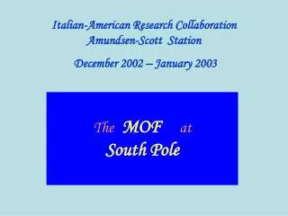
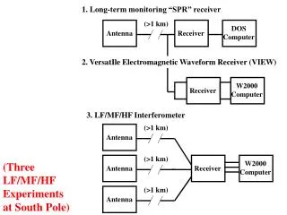
LF/MF/HF Receivers at South Pole Station. (>1 km). (>1 km). (>1 km). Antenna. Antenna. Antenna. 1. Long-term monitoring “SPR” receiver. (>1 km). DOS Computer. Antenna. Receiver. 2. VersatIle Electromagnetic Waveform Receiver (VIEW). W2000 Computer. Receiver.

E N D
LF/MF/HF Receivers at South Pole Station (>1 km) (>1 km) (>1 km) Antenna Antenna Antenna 1. Long-term monitoring “SPR” receiver (>1 km) DOS Computer Antenna Receiver 2. VersatIle Electromagnetic Waveform Receiver (VIEW) W2000 Computer Receiver 3. LF/MF/HF Interferometer W2000 Computer (Three LF/MF/HF Experiments at South Pole) Receiver
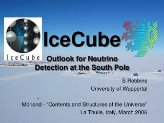
South Pole July 1, 2004 (Ye et al., JGR, 2006)
South Pole August 22, 2003 (Ye & LaBelle, JGR, 2007)
H fpe, fce 2. Mode conversion of long wavelength hiss: • Mode conversion of • Langmuir waves: Hiss on resonance cone meter-scale irregularity Hiss with nearly vertical k-vector free-space EM waves in atmosphere wparent-hiss = wirreg + wproduct kparent-hiss = kirreg + kproduct (rocket observations of Samara et al., 2006)
Future at South Pole/AGOs LF/MF/HF Interferometry ---requires low inteference at AM band and below ---requires lots of real estate! (> .5 km2) ---high latitude sites (>65-67 invariant) ---triangulation between sites desirable (S Pole---AGOs) ---Low power for AGO application 500 m
Kaktovik Toolik Lake Toolik Lake Interferometer Summer ’06.
TOOLIK 03-27-07 5 A 4 B D A C 3 Frequency in MHz 2 1 0 Time UT
TOOLIK 03-27-07 5 B 4 B D A C 3 Frequency in MHz 2 1 0 Time UT
TOOLIK 03-27-07 5 C 4 B D A C 3 Frequency in MHz 2 1 0 Time UT
TOOLIK 03-27-07 5 D 4 B D A C 3 Frequency in MHz 2 1 0 Time UT
TOOLIK 03-27-07 5 4 3 Frequency in MHz 2 1 0 Time UT
TOOLIK 04-28-07 5 4 3 Frequency in MHz 2 1 0 Time UT
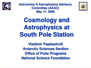
5 5 Amundsen-Scott South Pole Station, Antarctica 3 2 1 0 4 4 June 6 2004 June 6 2005 June 6 2006 3 3 2 2 1 1 0 0 00 UT 08 UT 16 UT 24 UT 3 2 1 0 Frequency (MHz) Frequency (MHz) 00 UT 08 UT 16 UT 24 UT 5 5 3 2 1 0 4 4 3 3 2 2 1 1 0 0 00 UT 08 UT 16 UT 24 UT 00 UT 08 UT 16 UT 24 UT 3 2 1 0 May 17 2007 00 UT 08 UT 16 UT 24 UT
Plans for this season at ‘Pole: • Dartmouth Personnel (N. Bunch) at South Pole in Jan ’08. • Map radio noise around South Pole Station (2-D grid of data pts). • Custom “Super Sniffer” – will provide quantitative indication of radio noise in several selected bands. • Determine antenna locations and assess need for “satellite station.”