Download

1 / 19
190 likes | 339 Views
EEMC perspectives @ STAR. Run 3 hardware calibration trigger software Run 4 expectations goals. Jan Balewski, IUCF, Indiana. STAR Collaboration Meeting MSU, August 2003. Upper Structure Mounted 8/1/2003. Instrumentation for pp Run 3. Pb Scint sampling calorimeter

E N D
EEMC perspectives @ STAR • Run 3 • hardware • calibration • trigger • software • Run 4 • expectations • goals Jan Balewski, IUCF, Indiana STAR Collaboration Meeting MSU, August 2003 Upper Structure Mounted 8/1/2003
Instrumentation for pp Run 3 • Pb Scint sampling calorimeter • 21 radiation lengths • 240 of 720 projective towers • Depth Segmentation • 2 preshower layers • High position resol. SMD • Postshower layer (no readout) • L0 trigger: • high tower (working) • jet patches (problems) 6 GeV electron preshower SMD U,V post 8 5 7 6
EEMC Calibration Summary from 2003 STAR p+p Data Three completely independentabsolute calibration approaches agree at the 10-20% level: MIP peak location, assuming 5.0% sampling fraction (as per simulations); reconstructed 0 invariant mass from EEMC towers alone; p/E from TPC-tracked electrons to EEMC. “Isolated MIP slopes” used online gave reasonable gain matching for different bins at given . Note: • 0 reconstruction (after correction for simulated systematic shift for very asymmetric decays) and MIP peaks give consistent relative gains vs. . • “Bootstrapping” approach, based on cosmic rays, 60Co source, and isolated MIP’s did not achieve desired ET matching or absolute gains! Following data from: R. Fatemi, J.Webb, P.Zolnierczuk, and J.B. THANKS !
Relative Gains from MIP’s For towers where clear MIP peak not visible, or tracking not available, use slope of tower ADC spectrum in anti-coincidence with neighboring towers as measure of relative gain. This is correlated very well with MIP peak location where both available. Pre calibration used in pp Run 3 For 1.0 1.5 , use MIP’s tracked from TPC to EEMC, where track predicted to enter and exit same tower. Landau fit to observed peak shape determines absolute gain of each tower illuminated, using 5.0% sampling fraction to convert to equivalent shower energy. =1.5 =1.0 • L3 tracks & • vertex used • off-line
EEMC Response to Tracked Electrons • Use TPC dE/dx vs. p to select track region where electrons are (slightly) dominant. • Use window on pions over same p range to estimate background EEMC response L3 tracks, vertex, dE/dx used off-line • Take relative tower gains from MIP’s, and adjust overall absolute calibration constant to match EEMC E to TPC p. • With presently available statistics, this gives (55 ± 5) channels/ GeV on ‘calibration’ tower 5TB09.
Electrons Trigger EHT-1,2 electrons Identified electrons w/ bckg used K=50 ch/GeV MinB trigger (2 M eve) p/E 1 2 0 10 E=3.3 GeV • L2 Enrichment (potential) • select trig tower and • require pre1 ~pre2 MIP • veto postshower • not tested with M-C • no data to play with • factor 10 would do EHT1 trigger (540 K eve) 0 10 E=5.5 GeV EHT2 trigger (140 K eve) Electron Energy reco in EEMC (GeV)
EEMC (Tower Only) 0 Reconstruction 1 0 2 - Invariant Mass 0 Total Energy 0 Energy Sharing raw data ‘diff ’ MinB Trigger data <M>=149 MeV =69 MeV M-C pi0 E=2 GeV mix diff M-C pi0 E=6GeV M-C pi0 E=8 GeV <M>=192 MeV =45 MeV EHT-1&2 Trigger data data ‘diff ‘ invM (GeV) Reco ener (GeV) Z invM12* (E1* E2) E1- E2 Z0= —––– E1+ E2 12 • Cuts: • seed >0.7 GeV • seed/cluster >0.7
Reconstruction of 0 with Limited Angular Resolution 1 E1- E2 Z0= —––– E1+ E2 0 • Cuts: • seed >0.7 GeV • seed/cluster >0.7 invM12* (E1* E2) 12 2 MinB trigger yields symmetric decayed 0 Seed thr 0 0.7 GeV Tower energy 0 E1= E2= 1 E’1= E1 12*{ E1* E2 (E1- E2)} m0 Z0 0 Seed-1 Overlap error E’2= E1 – + 2 GeV 0 Seed-2 High Tower trigger yields asymmetric decayed 0 trigger thr 0 0.7 3.5 GeV Tower energy E1=7 E’1= E1 – E1 Seed-1 E2=1 E’2= E2 + E1 Mostly overestimated Seed-2 8 GeV 0 =7 12*{ E1* E2 + E12} m0 *(1+ E1/ E2) Z0 0.8
-dependent Gains from Reconstructed 0 ( ) 2 invM M pi0 Simulated pi0 E=8 GeV Measured w/ SF=50 ch/GeV Events sorted according to bin of the higher-energy cluster. • Data here triggered by EEMC high-tower in p+p. =2.0 =1.0 • “Correct” mass determined from simulations, which take account of geometric effects and imperfect E sharing between clusters for the very asymmetric (E1 / E2 7:1) decays that satisfy high tower trigger + tower min. open. • Relative gains within each bin taken from MIP response. Absolute gains will be adjusted to place reconstructed 0peak at “correct” mass.
EEMC Towers Calibration Run 3 p+p Slopes ~ -1/gain on-line Goal ‘slopes‘ from the source scan =1.0 =1.0 =2.0 =2.0 slopes MIPs from electrons Tower Calibration (ch/GeV) Desired ET matched gains off-line =2.0 =1.0 -bin Number • Tower Gains in Run 3 • flat in energy ~50-60 ADC ch/GeV • known from MIP or slope 10% (stdev) • HV matched 20% (stdev)
EEMC Trigger in Run 3 • Jet Trigger problems • ped close to N*16 – fixed in FEE • correlated noise N*256 – veto Ejet>200 GeV • correlated ghost ped - ? • 1% data corruption - ? TP ID No hot channels Ghost Ped TP input to DSM CRATE 3, FEE CH 42 no detector ! ADC value • High Tower Trigger OK • EHT1 @ E=3.3 GeV • slow 600 K events • fast 300 K events • EHT2 @ E=5.5 GeV • slow 140 K events EHT-1 3.3 GeV EHT-2 5.5 GeV tower ID ADC value
EEMC (Tower) Database for Run 3 • On-line • monitor HV every 5 minutes • record any change for any tube • Off-line • map of FEE channel vs. tower • gains, one set from day 120+ • ped, new set each RHIC fill, • (changes below 1 ADC ch) • available in root4star Plot for 20 tubes HV (V) No change May 1-June 15 Days in 2003
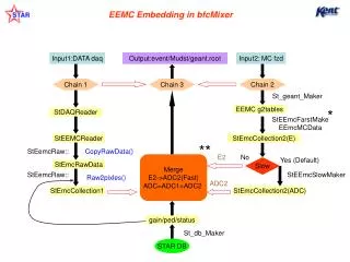
Software & Simulations (done) • Software • EEMC geometry in GSTAR (Oleg Rogachevski) • fast simulator for towers/ pre/ post/ SMD • DAQ reader (tower energy, Herb) • DAQ ezTree ( Piotr) • StEvent (Akio) • StEvent muDst (Alex) • Data sets • DAQ pp200 (towers): • 2 M minB events • 1 M EHT-1/2 • (available in ezTree format) • M-C PYTHIA, geom2003: • 1.3 M minB • 0.5 M partonic pT>5 GeV • 0.5 M partonic pT>15 GeV
View from IR towards West (along Z-axis) Run 4 Instrumentation 1 2 3 4 5 6 SMD 7 8 9 10 … 24 Layer: 1 Incident particles 2 6 3 5 4 1 ch 16 ch 16 ch PMT tower MAPMT Pre1,2,Post MAPMT SMD strips West North South • L0 trigger: • high tower • jet patches • readout • 720 towers • 5/12 pre/post • 5/12 SMD
Run 4 Calibration Plan • Goals: • towers 10% (used in trigger) • Pre/post/SMD 50% (in the range of ADC) • Commissioned 240 towers • fix ~10 dead ch • change gain to ET-match with LED • check gains with MIP and pi0 • New pre- post- shower, SMD • verify mapping: LED (or sourse) • set initial HV based on known gains • in beam set gains with MIP • for SMD try pi0 • pre/post: gains set high to see 1.e.e. ? • New 480 towers • before beam • set initial HV based on known gains • verify all channels with LED/laser • in beam (early) • use ‘slopes’ , gain match 50% • (ET-match to calibrated towers ) • use pi0 in dedicated run to gain match 10% • off-line • MIP, pi0, electrons
Physics Goals of Run 4 • contribute to jet trigger @ eta>1 • contribute to J/Psi and/or Upsilon in AuAu • trigger on high energy gamma • reco pi0 up to ~20 GeV • deal with pileup
Detailed Software Tasks • Slow control: (Wei Ming/Valpo) • - gui+VME HV sys • - STAR alarm: HV & FEE ped • - laser control • - main EEMC gui – DSM, Tower, SMD • - documentation for shifts • - ped loaded to trigger FEEonline DB • - MAPMT box temperature • SMD/Pre/Post Commissioning: (Scott/Steve ) • online histos : (Dave and Hal) • - define & implement (Paniatkin plots) • display : (Paul Nord?/Valpo) • - EEMC on L3 screen or • - automate tower+SMD+pre/post+track (online) • - (predict) fired SMD strips with LED pulser • calibration : (Piotr/Jan/Wei Ming) • - Pedestals: smd/pre/post - duplicate tower code • - Gains: pre/post - duplicate tower code for MIP • SMD – MIP finder code exist • write to DB, test • off-line database (Jan/Piotr) • - pre/post : duplicate tower info • - SMD : as tower + box mapping • calibration code (SMD) (Wei Ming) • - access in root4star ? • L2 programming : (Renee/Steve/Jason) • - enriched calibration trigger (pi0/e/MIP) • tracking at eta>1.5 : (MIT/Jason) • - not existing, use ITTF • merge hits: (ANL/Valpo/Piotr) • - pi0 reco at ~20 GeV • - pi0/gamma/hadrons ID • EEMC contribution to jet energy (Renee) • trigger simulator (Renee) Join us ! STAR tasks list: www.star.bnl.gov/STAR/Comp/general/task.html
Unsupported Software Tasks • pre/post/SMD data StEvent • pi0 reco : port FPD algo (tw+smd) • EEMC slow simulator • EEMC embedding • vertex reco : • integration with ITTF • pileup : B+E-EMC, SVT • display : EEMC on L3 plasma-screen Join us !