Download

1 / 25
250 likes | 420 Views
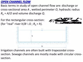
1. 1,2. Qianlong Liu & Andrea Prosperetti. 1. Department of Mechanical Engineering Johns Hopkins University, USA. Department of Applied Science University of Twente, The Netherlands. 2. Pressure-driven Flow in a Channel with Porous Walls. Funded by NSF CBET-0754344. Results :

E N D
1 1,2 Qianlong Liu & Andrea Prosperetti 1 Department of Mechanical Engineering Johns Hopkins University, USA Department of Applied Science University of Twente, The Netherlands 2 Pressure-driven Flow in a Channel with Porous Walls Funded by NSF CBET-0754344
Results : • Detailed flow structure • Hydrodynamic force/torque • Dependence on Re • Lift Force on spheres • Slip Condition vs. Beavers-Joseph model Numerical Method: PHYSALIS, combination of spectral and immersed boundary method (See JFM paper submitted) • Spectrally accurate near particle • No-slip condition satisfied exactly • No integration needed for force and torque
Flow Field • Re = 0.833 • y/a=0.8,0.5,0.3,0 • Streamlines on the symmetry midplane and neighbor similar to 2D case • At outermost cut, open loop similar to 2D results at small volume fraction • 2D features
Flow Field • Re = 83.3 • y/a=0.8,0.5,0.3,0 • Marked upstream and downstream • Clear streamline separation from the upstream sphere and reattachment to the downstream one • Different from 2D features
Flow Field • Re = 833 • y/a=0.8,0.5,0.3,0 • More evident features • Three-dimensional separation
Pressure Distribution • Pressure on plane of symmetry for Re=0.833, 83.3, 833 • High and low pressures near points of reattachment and separation • Maximum pressure smaller than minimum pressure • Point of Maximum pressure lower than that of minimum pressure • Combination of these two features contributes to a lift force
Horizontally Averaged Velocity • In the porous media for Re=0.833, 83.3, 833 • Two layers of spheres • Below the center of the top sphere, virtually identical averaged velocity • Consistent to experimental results of the depth of penetration
Horizontally Averaged Velocity • In the channel for Re=0.833, 83.3, 833 • Circles: numerical results • Solid lines: parabolic fit allowing for slip at the plane tangent to spheres • A parabolic-like fit reproduces very well mean velocity profile
Hydrodynamic Force • Normalized lift force as a function of the particle Reynolds number • Total force, pressure and viscous components • Dependence of channel height and porosity is weak, implying scales adequately capture the main flow phenomena • Slope 1: Low Re • Constant: High Re
Hydrodynamic Torque • Normalized Torque as a function of the particle Reynolds number • Decease with increasing Re_p in response to the increasing importance of flow separation • Weak dependence on channel height H/a=10, 12 • Dependence on volume fraction, although weak
Slip Condition Beavers-Joseph model modified model • Using Beavers-Joseph model, different results for shear- and pressure-driven flows • Modified with another parameter • Good fit of experimental results
Conclusions • Finite-Reynolds-number three-dimensional flow in a channel bounded by one and two parallel porous walls studied numerically • Detailed results on flow structure • Hydrodynamic force and torque • Dependence on Reynolds number • Lift force on spheres • Modification of slip condition
small Re Re const. large Re Rotation Axis Wall: Force • force directed toward the plane • low pressure between the sphere and the wall Re
Rotation Axis Wall: Couple • low Re: torque increases by wall-induced viscous dissipation • high Re: velocity smaller on wall side: dissipation smaller Re
Rotation Axis Wall: Streamsurfaces • Re=50 • Re=1
Force Normal to Wall • force in wall direction: sign change • lowRe: viscous repulsive force pushes particle away from the wall • highRe: attractive force from Bernoulli-type effect Re
Force Parallel to Wall • force in z direction: complex, sign change • low Re: negative, viscous effect dominates • high Re: positive to negative Re
Approximate Force Scaling • force in x and z directions • Scaling of gap: collapse
Unbounded Flow: couple • Hydrodynamic couple for rotating sphere in unbounded flow • Accurate results • Zero force
Unbounded Flow: maximum w • Poleward flow exert equal and opposite forces • Wall: destroy the symmetry • Continuity equation: Thus, Re
Perpendicular Wall: Pathline • Start near the wall, spirals up and outward toward the rotating sphere, and spirals back toward the wall • Resides on a toroidal surface