Download
1 / 37
370 likes | 556 Views
Custom Instruction Generation Using Temporal Partitioning Techniques for a R econfigurable Functional Unit. Farhad Mehdipour † , Hamid Noori †† , Morteza Saheb Zamani † , Kazuaki Murakami †† , Koji Inoue †† , Mehdi Sedighi †

E N D
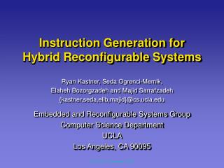
Custom Instruction Generation Using Temporal Partitioning Techniques for a Reconfigurable Functional Unit Farhad Mehdipour†, Hamid Noori††, Morteza Saheb Zamani†, Kazuaki Murakami††, Koji Inoue††, Mehdi Sedighi† †Computer and IT Engineering Department, Amirkabir University of Technology {mehdipur,szamani,msedighi}@aut.ac.ir ††Department of Informatics, Graduate School of Information Science and Electrical Engineering, Kyushu University noori@c.csce.kyushu-u.ac.jp, {murakami,inoue}@i.kyushu-u.ac.jp
Agenda • Introduction • Application-specific instruction set extension • Temporal Partitioning • Some Definitions • General overview of the architecture • RFU Architecture: A Quantitative Approach • Generating Custom Instructions • Mapping Custom Instructions • Integrating RFU with base processor • Integrated framework for generating and mapping custom instructions • Performance Evaluation • References
Introduction • An extensible processor with a reconfigurable functional unit (RFU) • can be an alternative to General Purpose Processors (GPPs), Application-Specific Integrated Circuits (ASICs) and Application-Specific Instruction set Processors (ASIPs) • to achieve enhanced performance in embedded systems • ASICs • not flexible • expensive and time consuming design process • GPPs • very flexible • may not offer the necessary performance
Introduction • ASIPs • more flexible than ASICs • more potential to meet the high-performance demands of embedded applications, compared to GPPs • needs to generation of a complete instruction set architecture for the targeted application • full-custom solution is too expensive and has long design turnaround times
Application-specific instruction set extension • Another Method for performance improvement • An extensible processor with a reconfigurable functional unit • favorable tradeoff between efficiency and flexibility • keeping design turnaround time much shorter. • Critical portions of an application’s dataflow graph (DFG) are accelerated by using custom functional units • The nodes of DFGs -> instructions of critical potions • Edges of DFGs -> dependencies between instructions
Temporal Partitioning • Partitioning a data flow graph into a number of partitions such that • each partition can fit into the target hardware and • dependencies among the graph nodes are not violated.
Some definitions • Hot Basic Block (HBB) • A basic block which execution frequency is greater than a given threshold specified in the profiler • Custom Instructions (CIs) • Are the extended Instruction Set Architecture (ISA) that are executed on the RFU • Reconfigurable Functional Unit (RFU) • Custom hardware for executing CIs
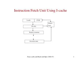
General overview of the architecture Adaptive Dynamic Extensible Processor N-way in-order general RISC Detects start addresses of Hot Basic Blocks (HBBs) Base Processor Fetch Reg File Augmented Hardware Decode Switches between main processor and RFU Profiler Execute RFU Memory Sequencer Write Executes Custom Instructions
Operation modes Training Mode Training Mode Normal Mode Running Tools for Generating Custom Instructions, Generating Configuration Data for ACC and Initializing Sequencer Table Monitors PC and Switches between main processor and ACC Detecting Start Address of HBBs Applications Applications Applications Binary-Level Profiling Processor Processor Processor Profiler Profiler Profiler Profiler ACC ACC ACC Sequencer Sequencer Sequencer Binary Rewriting Executing CIs
Reconfigurable Functional Unit (RFU) • RFU is a matrix of Functional Units (FUs) • RFU has a two level configuration memory • A multi-context memory (keeps two or four config) • A cache • FUs support only logical operations, add/subtract, shifts and compare • RFU updates the PC • RFU has variable delay which depends on size of Custom Instruction
RFU Architecture: A Quantitative Approach • 22 programs of MiBench were chosen • Simplescalar toolset was utilized for simulation • RFU is a matrix of FUs • No of Inputs • No of Outputs • No of FUs • Connections • Location of Inputs & Outputs • Some definitions: • Considering frequency and weight in measurement • CI Execution Frequency • Weight (To equal number of executed instructions) • Average = for all CIs (ΣFreq*Weight) • Rejection: Percentage of CI that could not be mapped on the RFU • Coverage: Percentage of CI that could be mapped on the RFU • Basic Blocks:A sequence of instructions terminates in a control instruction • Hot Basic Blocks: A basic block executed more than a threshold
RFU Architecture • Distributing Inputs in different rows • Row1 = 7 • Row 2 = 2 • Row 3 = 2 • Row 4 = 2 • Row 5 = 1 • Connections with Variable Length • row1 row3 = 1 • row1 row4 = 1 • row1 row5 = 1 • row2 row4 = 1 Synthesis results using Hitachi 0.18 μm Area : 1.1534 mm2 Delay : 9.66 ns
Integrating RFU with the Base Processor Reg0 Reg31 ………………………………………………………………. Config Mem Decoder Sequencer DEC/EXE Pipeline Registers FU1 FU2 FU3 FU4 RFU Sequencer EXE/MEM Pipeline Registers
Generation of Custom Instructions • Custom instructions • Exclude floating point, multiply, divide and load instructions • Include at most one STORE, at most one BRANCH/JUMP and all other fixed point instructions • Simple algorithm for generating custom instructions • HBBs usually include 10~40 instructions for Mibench • Custom instruction generator is going to be executed on the base processor (in online training mode)
Mapping Custom Instructions • Mapping is the same as the well-known placement problem: • Determining the appropriate positions for DFG nodes on the RFU. • Assigning CI instructions to FUs is done based on the priority of the nodes.
Mapping Custom Instructions • Slackof each node represents its criticalityand alsotheir priority for partitioning. • Slackequal to 0 means that it is on the critical path of DFG and should be scheduled with the highest priority. • For the nodes with the same criticality, ASAP level of them determines their mapping order.
Mapping Algorithm (1/2) • First Step: determining an appropriate row for that node • Row number= Last Row (if the selected node is on a critical path with the length more than or equal to RFU depth) • Row number= ALAP- slack -1(to prevent the occupation of FUs in the lower RFU rows by the nodes do not belong to critical paths )
Mapping Algorithm (2/2) • Second Step: Determining an appropriate column • That is determined according to the minimum connection length criterion. • For each row, a maximum capacity is considered to prohibit gathering many nodes in a row. • Capacity of rows is determined with respect to longest critical path and the number of critical paths in the DFG.
Generating Custom Instruction for the Target RFU • In our primary CI generator we did not consider any constraints for the generated CIs and tried to generate CIs as large as possible. • Therefore, some of the generated CIs can not be mapped on the proposed RFU due to its constraints.
Customizing CI generator for the Target RFU – First Approach • Some primary constraints of RFU (number of inputs, number of outputs and number of nodes) were added to our CI generator tool to generate CIs that are mappable. • In this approach the CI generator is unaware of the mapping process results • Some of CIs may not be ultimately mapped to the RFU due to the routing constraints
Customizing CI generator for the Target RFU – Second Approach • Integrated Framework • Performs an integrated temporal partitioning and mapping process • Takes rejected CIs as input • Partitions them to appropriate mappable CIs • Adds nodes to the current partition while architectural constraints are satisfied • The ASAP level of nodes represents their order to execute according to their dependencies • Advantages • Reducing the number of rejected CI • Using a mapping-aware temporal partitioning process
Integrated Framework- Temporal Partitioning Algorithms • HTTP • Traverses DFG nodes horizontally according to the ASAP level of the nodes • usually brings about more parallelism for instruction execution • may require large intermediate data • The size of intermediate data affects data transfer rate and the size of configuration memory. • VTTP • Traverse the DFG nodes vertically • Creates partitions with longer critical paths • Reduces the size of intermediate data
Integrated Framework- Incremental Temporal Partitioning Algorithm • Incremental temporal partitioning process is performed iteratively • Each partition which does not satisfy RFU constraints is modified • A new iteration starts. • Two different partition modification strategies are used for HTTP and VTTP • The main difference is in the way of selecting the nodes to be moved to the next partition.
Integrated Framework- Incremental Temporal Partitioning Algorithm • Incremental HTTP • The node with the highest ASAP level is selected and moved to the subsequent partition. • Nodes selection and moving order: 15, 13, 11, 9, 14, 12, 10, 8, 3 and 7.
Integrated Framework- Incremental Temporal Partitioning Algorithm • Incremental VTTP: • A node with the highest ASAP level is selected and moved. • The other nodes are selected from the path where the previous moved node had been located in their ASAP level order. • Nodes selection and moving order:15, 14, 6, 13, 12, 5, 11, 10, 4 and 7.
Customizing Mapping Tool Spiral shaped mapping is possible thanks to the horizontal connections in the third and fourth rows of RFU
Performance Evaluation • Simplescalar was configured to behave as a 4-issue in-order RISC processor. The base processor supports MIPS instruction set. • 22 applications of Mibench
Delay of RFU according to CI length • Synopsys Tools + Hitachi 0.18μm
References • Arnold, M., Corporaal, H., Designing domain-specific processors. In Proceedings of the Design, Automation and Test in Europe Conf, 2001, pp. 61-66. • Atasu, K., Pozzi, L., Lenne, P., Automatic application-specific instruction-set extensions under microarchitectural constraints, 40th Design Automation Conference, 2003. • Bobda, C., Synthesis of dataflow graphs for reconfigurable systems using temporal partitioning and temporal placement, Ph.D thesis, Faculty of Computer Science, Electrical Engineering and Mathematics, University of Paderborn, 2003. • Clark, N., Kudlur, M., Park, H., Mahlke, S., Flautner, K., Application-Specific Processing on a General-Purpose Core via Transparent Instruction Set Customization, In Proceedings of the 37th annual IEEE/ACM International Symposium on Microarchitecture, 2004. • Karthikeya, M., Gajjala, P., Dinesh, B., Temporal partitioning and scheduling data flow graphs for reconfigurable computer, IEEE Transactions on Computers, vol. 48, no. 6, 1999, pp.579–590.
References • Kastner, R. Kaplan, A., Ogrenci Memik, S., Bozorgzadeh, E., Instruction generation for hybrid reconfigurable systems, ACM TODAES, vol. 7, no. 4, 2002, pp. 605-627. • Ouaiss, I., Govindarajan, S., Srinivasan, V., Kaul M., Vemuri R., An integrated partitioning and synthesis system for dynamically reconfigurable multi-FPGA architectures, In Proceedings of the Reconfigurable Architecture Workshop, 1998, pp. 31-36. • Spillane, J., Owen, H., Temporal partitioning for partially reconfigurable field programmable gate arrays, IPPS/SPDP Workshops, 1998, pp. 37-42. • Tanougast, C., Berviller, Y., Brunet, P., Weber, S., Rabah, H., Temporal partitioning methodology optimizing FPGA resources for dynamically reconfigurable embedded real-time system, International Journal of Microprocessors and Microsystems, vol. 27, 2003, pp. 115-130. • Yu, P., Mitra, T., Characterizing embedded applications for instruction-set extensible processors, In Proceedings of Design and Automation Conference, 2004, pp. 723- 728.