Download
1 / 44
510 likes | 1.06k Views
Elastic Properties and Anisotropy of Elastic Behavior. Figure 7-1 Anisotropic materials: (a) rolled material, (b) wood, (c) glass-fiber cloth in an epoxy matrix, and (d) a crystal with cubic unit cell.

E N D
Figure 7-1 Anisotropic materials: (a) rolled material, (b) wood, (c) glass-fiber cloth in an epoxy matrix, and (d) a crystal with cubic unit cell.
Real materials are never perfectly isotropic. In some cases (e.g. composite materials) the differences in properties for different directions are so large that one can not assume isotropic behavior - Anisotropic. • There is need to discuss Hooke’s Law for anisotropic cases in general. This can then be reduced to isotropic cases - material property (e.g., elastic constant) is the same in all directions.
In the general 3-D case, there are six components of stress and a corresponding six components of strain. • In highly anisotropic materials, any one component of stress can cause strain in all six components. • For the generalized case, Hooke’s law may be expressed as: where, • Both Sijkl and Cijkl are fourth-rank tensor quantities. (7-1) (7-2)
Expansion of either Eqs. 7-1 or 7-2 will produce nine (9) equations, each with nine (9) terms, leading to 81 constants in all. • It is important to note that both ij and ij are symmetric tensors. • Symmetric tensor Means that the off-diagonal components are equal. For example, in case of stress:
We can therefore write: (7-3)
Symmetry effect leads to a significant simplification of the stress-strain relationship of Eqs. 7-1 and 7-2. We can write: We can also write: and since
The direct consequence of the symmetry in the stress and strain tensors is that only 36 components of the compliance tensor are independent and distinct terms. • Similarly, only 36 components of the stiffnesstensor are independent and distinct terms.
Additional simplification of the stress-strain relationship can be realized through simplifying the matrix notation for stresses and strains. We can replace the indices as follows: 11 12 13 1 6 5 22 23 2 4 33 3 = Notation II Notation I
The foregoing transformation is easy to remember: In other to obtain notation II, one must proceed first along the diagonal ( ) and then back ( ). • Notation II method makes life very easy when correlating the stresses and strains for general case, in which the elastic properties of a material are dependent on its orientations.
It should be noted that , and , but (7-5)
In matrix format, the stress-strain relation showing the 36 (6 x 6) independent components of stiffness can be represented as: Or in short notation, we can write: (7-6)
Further reductions in the number of independent constants are possible by employing other symmetry considerations to Eq. 7-6. • Symmetry in Stiffness and Compliance matrices requires that: Of the 36 constants, there are six constants where i = j, leaving 30 constants where i j. But only one-half of these are independent constants since Cij = Cji Therefore, for the general anisotropic linear elastic solid there are: independent elastic constant.
The 21 independent elastic constants can be reduced still further by considering the symmetry conditions found in different crystal structures. • In Isotropic case, the elastic constants are reduced from 21 to 2. • Different crystal systems can be characterized exclusively by their symmetries. Table 7-1 presents the different symmetry operations defining the seven crystal systems. • The seven crystalline systems can be perfectly described by their axes of rotation. For example, a threefold rotation is a rotation of 120o (3 x 120o = 360o); after 120o the crystal system comes to a position identical to the initial one.
Table 7.1 Minimum Number of Symmetry Operations in Various Systems ______________________________________________ System Rotation ______________________________________________ Triclinic None (or center of symmetry) Monoclinic 1 twofold rotation Orthorhombic 2 perpendicular twofold rotation Tetragonal 1 fourfold rotation around [001] Rhombohedral 1 threefold rotation around [111] Hexagonal 1sixfold rotation around [0001] Cubic 4 threefold rotations around <111>
The hexagonal system exhibits a sixfold rotation around the [0001] - c axis; after 60 degrees, the structure superimposes upon itself. In terms of a matrix, we have the following: OrthorhombicTetragonal (7.7a)
Hexagonal (7.7b) where or
Laminated composites made by the consolidation of prepregged sheets, with individual piles having different fiber orientations, have orthotropic symmetry with nine independent elastic constant. • This is analogous to orthorhombic symmetry, and possess symmetry about three orthogonal (oriented 90o to each other) planes. The elastic constants along the axes of these three planes are different.
Cubic (7.7c) The number of independent elastic constants in a cubic system is three (3). For isotropic materials ( most polycrystalline aggregates can be treated as such) there are two (2) independent constants, b/c : (7.8)
For cubic systems, Equation (7-8) does not apply, and we define an anisotropy ratio (also called the Zener anisotropy ratio, in honor of the scientist who introduced it): (7.10) • Several metals have high “A” anisotropy ratio. • Aluminum and tungsten, have values of A very close • to 1. Single crystals of tungsten are almost isotropic.
Elastic compliances - for the isotropic case: (7.11) Similarly, the 81 components of elastic compliance for the cubic system have been reduced to three (3) independent ones while for the isotropic case, only two (2) independent elastic constants are needed.
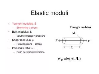
The elastic constants for an isotropic material are given by: Young’s modulus (7.12) Rigidity or Shear modulus (7.13)
Compressibility (B) and bulk modulus (K): (7.14) Poisson’s ratio (7.15) Lame’s constants: (7.16) (7.17)
The equation to determine the compliance of isotropic materials can be written as (by using Eqs. 7-2 and 7-11): (7.18)
The relationship of Eq. 7-18 can be expanded and equated to Eq. 6-9 to give: (7.19)
Also, (7.19)
Expressing the strains as function of stresses, we have (7.20)
A great number of materials can be treated as isotropic, • although they are not microscopically so. • Individual grains exhibit the crystalline anisotropy and • symmetry, but when they form a poly-crystalline aggregate • and are randomly oriented, the material is microscopically • isotropic. • If the grains forming the poly-crystalline aggregate have • preferred orientation, the material is microscopically • anisotropic. • Often, material is not completely isotropic; if the • elastic modulus E is different along three perpendicular • directions, the material is Orthotropic; composites are a • typical case.
In a cubic material, the elastic moduli can be determined along any orientation, from the elastic constants, by the application of the following equations: (7.21a) (7.21b) and are the Young’s and shear modulus, respectively, in the [ijk] direction; are the direction cosines of the direction [ijk]
Table 7-2 Stiffness and compliance constants for cubic crystals ___________________________________________________ Metal ___________________________________________________ Aluminum 10.82 6.13 2.85 1.57 -0.57 3.15 Copper 16.84 12.14 7.54 1.49 -0.62 1.33 Iron 23.70 14.10 11.60 0.80 -0.28 0.86 Tungsten 50.10 19.80 15.14 0.26 -0.07 0.66 ___________________________________________________ Stiffness constants in units of 10-10 Pa. Compliance in units of 10-11 Pa
Using the direction cosines l, m, n (as described in the text book) the equation for determining the Elastic Moduli along any direction is given by: (7.22) Typical values of elastic constants for cubic metals are given in Table 7.2. All the relations described in Eqs. 7-12 to 7-20 for obtaining Elastic constants are applicable. This include:
Example A hydrostatic compressive stress applied to a material with cubic symmetry results in a dilation of -10-5. The three independent elastic constants of the material are C11 = 50 GPa, C12 = 40 GPa and C44 = 32 GPa. Write an expression for the generalized Hooke’s law for the material, and compute the applied hydrostatic stress.
SOLUTION Dilation is the sum of the principal strain components: = 1 + 2 + 3 = -10-5 Cubic symmetry implies that 1 = 2 = 3 = -3.33 x10⁻⁵ and 4 = 5 = 6 = 0 From Hooke’s law, i = Cijj and the applied hydrostatic stress is: p = 1 = (50 + 40 + 40)(-3.33) 103 Pa = -130 x 3.33 x 103 = -433 kPa
Example: Determine the modulus of elasticity for tungsten and iron in the <111> and <100> directions. What conclusions can be drawn about their elastic anisotropy? From Table 7.1 ____________________________ ________________ Fe: 0.80 -0.28 0.86 W: 0.26 -0.07 0.66
SOLUTION The direction cosines for the chief directions in a cubic lattice are: _______________________________________ Directions _______________________________________ <100> 1 0 0 <110> 0 <111>
Therefore, we see that tungsten is elastically isotropic while iron is elastically anisotropic.