Download
1 / 25
250 likes | 345 Views
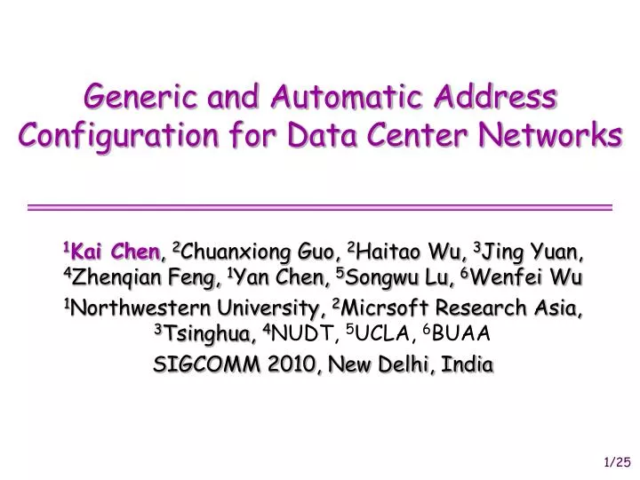
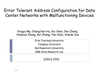
Generic and Automatic Address Configuration for Data Center Networks. 1 Kai Chen , 2 Chuanxiong Guo, 2 Haitao Wu, 3 Jing Yuan, 4 Zhenqian Feng, 1 Yan Chen, 5 Songwu Lu, 6 Wenfei Wu 1 Northwestern University, 2 Micrsoft Research Asia, 3 Tsinghua, 4 NUDT, 5 UCLA, 6 BUAA

E N D
Generic and Automatic Address Configuration for Data Center Networks 1Kai Chen, 2Chuanxiong Guo, 2Haitao Wu, 3Jing Yuan, 4Zhenqian Feng, 1Yan Chen, 5Songwu Lu, 6Wenfei Wu 1Northwestern University, 2Micrsoft Research Asia, 3Tsinghua, 4NUDT, 5UCLA, 6BUAA SIGCOMM 2010, New Delhi, India
Motivation • Address autoconfiguration is desirable in networked systems • Manual configuration is error-prone • 50%-80% network outages are due to manual configuration • DHCP for layer-2 Ethernet autoconfiguration • Address autoconfiguration in data centers (DC) has become a problem • Applications need locality information for computation • New DC designs encode topology information for routing • DHCP is not enough - no such locality/topology information
Research Problem Given a new/generic DC, how to autoconfigure the addresses for all the devices in the network? DAC: data center address autoconfiguration
Outline • Motivation • Research Problem • DAC • Implementation and Experiments • Simulations • Conclusion
DAC Input • Blueprint Graph (Gb) • A DC graph with logical IDs • Logical ID can be any format • Available earlier and can be automatically generated • Physical Topology Graph (Gp) • A DC graph with device IDs • Device ID can be MAC address • Not available until the DC is built and topology is collected 10.0.0.3 00:19:B9:FA:88:E2
DAC System Framework Malfunction Detection Physical Topology Collection Device-to-logical ID Mapping Logical ID Dissemination
Two Main Challenges • Challenge 1: Device-to-logical ID Mapping • Assign a logical ID to a device, preserving the topological relationship between devices • Challenge 2: Malfunction Detection • Detect the malfunctioning devices if the physical topology is not the same as blueprint (NP-complete and even APX-hard)
Roadmap Malfunction Detection Physical Topology Collection Device-to-logical ID Mapping Logical ID Dissemination
Device-to-logical ID Mapping • How to preserve the topological relationship? • Abstract DAC mapping into the Graph Isomorphism (GI) problem • The GI problem is hard: complexity (P or NPC) is unknown • Introduce O2: a one-to-one mapping for DAC • O2 Base Algorithm and O2 Optimization Algorithm • Adopt and improve techniques from graph theory
O2 Base Algorithm Gb:{l1 l2 l3 l4 l5 l6 l7 l8} Gp:{d1 d2 d3 d4 d5 d6 d7 d8} Decomposition Gb:{l1} {l2 l3 l4 l5 l6 l7 l8} Gp:{d1} {d2 d3 d4 d5 d6 d7 d8} Refinement Gb:{l1} {l5}{l2 l3 l4 l6 l7 l8} Gp:{d1} {d2 d3 d5 d7}{d4 d6 d8}
O2 Base Algorithm Gb:{l1 l2 l3 l4 l5 l6 l7 l8} Gp:{d1 d2 d3 d4 d5 d6 d7 d8} Decomposition Gb:{l5} {l1 l2 l3 l4 l6 l7 l8} Gp:{d1} {d2 d3 d4 d5 d6 d7 d8} Refinement Gb:{l5} {l1 l2 l7 l8}{l3 l4 l6 } Gp:{d1} {d2 d3 d5 d7}{d4 d6 d8} Refinement Gb:{l5} {l1 l2 l7 l8} {l6}{l3 l4} Gp:{d1} {d2 d3 d5 d7} {d6}{d4 d8}
O2 Base Algorithm Refinement Gb:{l5} {l6}{l1 l2}{l7 l8}{l3 l4} Gp:{d1} {d6}{d2 d7}{d3 d5}{d4 d8} Decomposition Gb:{l5} {l6}{l1}{l2}{l7 l8}{l3 l4} Gp:{d1} {d6}{d2}{d7}{d3 d5}{d4 d8} Decomposition & Refinement Gb: {l5} {l6}{l1}{l2}{l7}{l8}{l3}{l4} Gp:{d1} {d6}{d2}{d7}{d3}{d5}{d4}{d8}
O2 Base Algorithm • O2 base algorithm is very slow for 3 problems: • P1: Iterative splitting in Refinement: • it tries to use each cell to split every other cell iteratively • Gp: π1π2π3……πn-1πn • P2: Iterative mapping in Decomposition: • when the current mapping is failed, it iteratively selects the next node as a candidate for mapping • P3: Random selection of mapping candidate: no explicit hint for how to select a candidate for mapping
O2 Optimization Algorithm R1: A cell cannot split another cell that is disjoint with itself. R2: If u in Gb cannot be mapped to v in Gp, then all nodes in the same orbit with u cannot be mapped to v either. • Heuristics based on DC topology features • Sparse => Selective Splitting (for Problem 1) • Symmetric => Candidate Filtering via Orbit (for Problem 2) • Asymmetric => Candidate Selection via SPLD (Shortest Path Length Distribution) (for Problem3) • We propose the last one and adopt the first two from graph theory R3: Two nodes u, v in Gb, Gp cannot be mapped to each other if have different SPLDs.
Speed of O2 Mapping 8.9 seconds 12.4 hours 8.9 seconds
Roadmap Malfunction Detection Physical Topology Collection Device-to-logical ID Mapping Logical ID Dissemination
Malfunction Detection • Types of Malfunctions • Node failure, Link failure, Miswiring • Effects of Malfunctions • O2 cannot find device-to-logical ID mapping • Our Goal • Detect malfunctioning devices • Problem Complexity • An ideal solution • Find Maximum Common Subgraph (MCS) between Gb and Gp say Gmcs • Remove Gmcs from Gp => the rest are malfunctions • MCS is NP-complete and even APX-hard
Practical Solution Isomorphic Isomorphic 1 1 • Observations • Most node/link failures, miswirings cause node degree change • Special, rare miswirings happen without degree change • Our Idea • Degree change case: exploit the degree regularity in DC • Devices in DC have regular degrees (common sense) • No degree change case: probe sub-graphs derived from anchor points, and correlate the miswired devices using majority voting • Select anchor point pairs from 2 graphs • probe sub-graphs iteratively, stop when k-hop subgraphs are isomorphic but (k+1)-hop are not, increase the counters for k- and (k+1)- hop nodes • Output node counter list: high counter => high possible to be miswired 2 2 Isomorphic … … k k Non-Isomorphic k+1 k+1
Simulations on Miswiring Detection • Over data centers with tens of thousands of devices • with 1.5% nodes as anchor points to identify all hardest-to-detect miswirings 1.5%
Roadmap Malfunction Detection Physical Topology Collection Device-to-logical ID Mapping Logical ID Dissemination
Basic DAC Protocols • CBP: Communication Channel Building Protocol • Top-Down, from root to leaves • PCP: Physical Topology Collection Protocol • Bottom-Up, from leaves to root • LDP: Logical ID Dissemination Protocol • Top-Down, from root to leaves • DAC manager: • handle all the intelligences • can be any server in the network
Implementation and Experiments • Over a BCube(8,1) network with 64 servers • Communication Channel Building (CCB) • Transition time • Physical Topology Collection (TC) • Device-to-logical ID Mapping • Logical IDs Dissemination (LD) • The total time used: 275 milliseconds
Simulations • Over large-scale data centers (in milliseconds) 46 seconds for the DCell(6, 3) with 3.8+ million devices
Summary • DAC: address autoconfiguration for generic data center networks, especially when the address is topology-aware • Graph isomorphism for address configuration • 275ms for a 64-sever BCube, and 46s for a DCell with 3.8+ million devices • Anchor point probing for malfunction detection • with 1.5% nodes as anchor points to identify all hardest-to-detect miswirings • DAC is a small step towards the more ambitious goal of automanagement of the whole data centers
Q & A? Thanks!


![[IP address configuration BCP]](https://cdn1.slideserve.com/2707721/ip-address-configuration-bcp-dt.jpg)