Lecture 9. MIPS Processor Design – Decoding and Execution
2010 R&E Computer System Education & Research. Lecture 9. MIPS Processor Design – Decoding and Execution. Prof. Taeweon Suh Computer Science Education Korea University. Overview of CPU Design. mips_tb.v (testbench). mips_cpu_mem.v. mips_cpu.v. imem.v (Instruction Memory). reset.

Lecture 9. MIPS Processor Design – Decoding and Execution
E N D
Presentation Transcript
2010 R&E Computer System Education & Research Lecture 9. MIPS Processor Design – Decoding and Execution Prof. Taeweon Suh Computer Science Education Korea University
Overview of CPU Design mips_tb.v (testbench) mips_cpu_mem.v mips_cpu.v imem.v (Instruction Memory) reset Decoding Address fetch, pc Binary (machine code) Address Bus Instruction Memory MIPS CPU clock Instruction Data Bus Register File ALU Memory Access dmem.v (Data Memory) Address Bus Data Memory Address Data in your program, Stack, Heap DataOut Data Bus DataIn
Instruction Fetch • What is PC on reset? • MIPS initializes the PC to 0xBFC0_0000 • For the sake of simplicity, let’s initialize the PC to 0x0000_0000 in our design • How about x86 and ARM? • x86 reset vector is 0xFFFF_FFF0. BIOS ROM is located there • ARM reset vector is 0x0000_0000 MIPS CPU Core Increment by 4 for next instruction Add Instruction Memory reset clock 4 PC Out Address 32 instruction 32-bit register (flip-flops)
Instruction Decoding • Instruction Decoding • Separate the fetched instruction into the fields (according to the instruction types: R, I, and J types) • Opcode and funct fields determine which operation the instruction wants to do • Control logic needs to be designed to supply control signals to appropriate components (such as ALU and register file) inside CPU • Operands • Register addresses in the instruction are sent to the register file • Immediate field is either sign-extended or zero-extended depending on the instruction
32 32 Instruction Decoding Schematic MIPS CPU Core Control Unit Opcode funct ra1[4:0] rd1 Register File RegWrite ra2[4:0] R0 Add R1 wa[4:0] reset R2 clock Instruction Memory 4 rd2 PC R3 wd … instruction Out Address 32 R30 32 R31 RegWrite Sign or zero-extended imm 16 32
32 32 Register File in Verilog module regfile(input clk, input RegWrite, input [4:0] ra1, ra2, wa, input [31:0] wd, output [31:0] rd1, rd2); reg [31:0] rf[31:0]; // three ported register file // read two ports combinationally // write third port on rising edge of clock // register 0 hardwired to 0 always @(posedge clk) if (RegWrite) rf[wa] <= wd; assign rd1 = (ra1 != 0) ? rf[ra1] : 0; assign rd2 = (ra2 != 0) ? rf[ra2] : 0; endmodule 5 5 5 Register File ra1[4:0] rd1 32 bits ra2[4:0] R0 R1 wa R2 rd2 R3 wd … 32 R30 R31 RegWrite
Sign/Zero Extension in Verilog Why declares it as reg? Is it going to be synthesized as registers? Is this logic combinational or sequential logic? module sign_zero_ext(input sign_ext, input [15:0] a, output reg [31:0] y); always @(*) begin if (sign_ext) y <= {{16{a[15]}}, a}; else y <= {{16{1'b0}}, a}; end endmodule sign_ext Sign or zero-extended a[15:0] = imm y[31:0] 16 32
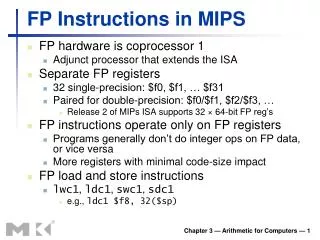
Instruction Execution #1 • Execution of the arithmetic and logical instructions • R-type arithmetic and logical instructions • Examples: add, sub, and, or ... • Operand sources • 2 Operands from the register file • I-type arithmetic and logical instructions • Examples: addi, andi, ori ... • Operand sources • 1 operand from the register file • 1 operand from the immediate field add $t0, $s1, $s2 opcode rs rt rd sa funct destination register addi $t0, $s3, -12 opcode rs rt immediate
32 32 Instruction Execution Schematic – Arithmetic and Logical Instructions MIPS CPU Core Control Unit Opcode funct ra1[4:0] ALUSrc rd1 Register File RegWrite ra2[4:0] R0 Add R1 wa[4:0] reset R2 clock Instruction Memory 4 rd2 PC R3 wd ALUSrc … instruction ALU Out Address 32 R30 32 mux R31 RegWrite Sign or zero-extended imm 16 32
How to Design Mux in Verilog? module mux2 (input [31:0] d0, d1, input s, output reg [31:0] y); always @(*) begin if (s) y <= d1; else y <= d0; end endmodule module mux2 (input [31:0] d0, d1, input s, output [31:0] y); assign y = s ? d1 : d0; endmodule OR Design it with parameter, so that this module can be used (instantiatiated) in any sized muxes in your design module datapath(………); wire [31:0] writedata, signimm; wire [31:0] srcb; wire alusrc // Instantiation mux2 #(32) srcbmux(writedata, signimm, alusrc, srcb); endmodule module mux2 #(parameter WIDTH = 8) (input [WIDTH-1:0] d0, d1, input s, output [WIDTH-1:0] y); assign y = s ? d1 : d0; endmodule
Instruction Execution #2 • Execution of the memory access instructions • lw, sw instructions lw $t0, 24($s3) // $t0 <= [$s3 + 24] opcode rs rt immediate sw $t2, 8($s3) // [$s3 + 8] <= $t2 opcode rs rt immediate
32 32 Instruction Execution Schematic with Memory Access Instructions MIPS CPU Core Control Unit MemtoReg Opcode funct MemWrite ra1[4:0] ALUSrc rd1 Register File RegWrite ra2[4:0] mux R0 Add MemWrite R1 wa[4:0] reset R2 clock Data Memory Instruction Memory 4 rd2 PC R3 wd ALUSrc WriteData … instruction ALU Out MemtoReg ReadData Address 32 R30 32 mux Address R31 Sign or zero-extended imm 16 32 lw $t0, 24($s3) // $t0 <= [$s3 + 24] sw $t2, 8($s3) // [$s3 + 8] <= $t2
Data Memory Verilog Model 64 words module dmem(input clk, MemWrite, input [31:0] Address, input [31:0] WriteData, output [31:0] ReadData); reg [31:0] RAM[63:0]; assign ReadData = RAM[Address[7:2]]; always @(posedge clk) begin if (MemWrite) RAM[Address[7:2]] <= WriteData; end endmodule Word (32-bit) MemWrite Data Memory WriteDat[31:0] 32 6 32 ReadData[31:0] Address
Instruction Execution #3 • Execution of the branch and jump instructions • beq, bne, j, jal, jr instructions beq $s0, $s1, Lbl // go to Lbl if $s0=$s1 opcode rs rt immediate Destination = (PC + 4) + (imm << 2) j target // jump opcode jump target Destination = {PC[31:28] , jump target, 2’b00}
32 32 Instruction Execution Schematic with “beq” Instruction MIPS CPU Core branch PCSrc Control Unit Opcode funct zero ra1[4:0] rd1 Register File ra2[4:0] mux R0 Add MemWrite Add R1 wa[4:0] reset R2 clock Instruction Memory Data Memory 4 rd2 R3 wd ALUSrc WriteData … instruction ALU Out MemtoReg PCSrc ReadData Address 32 R30 32 mux mux Address R31 <<2 Sign or zero-extended imm PC 16 32 Destination = (PC + 4) + (imm << 2)
32 32 Instruction Execution Schematic with “j” Instruction MIPS CPU Core jump branch PCSrc Control Unit Opcode funct zero ra1[4:0] rd1 Register File ra2[4:0] mux R0 Add MemWrite Add R1 wa[4:0] reset R2 clock Instruction Memory Data Memory 4 rd2 R3 wd ALUSrc WriteData … instruction ALU Out MemtoReg PCSrc jump ReadData Address 32 R30 32 mux mux mux Address R31 <<2 Sign or zero-extended imm imm PC <<2 J_addr 28 16 26 32 PC[31:28] Destination = {PC[31:28] , jump target, 2’b00}