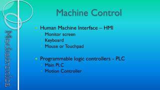
Machine control instruction
Explore essential program control instructions of a microprocessor, including HALT, NOP, WAIT, LOCK, flag manipulation, string operations, and control transfer commands like CALL and RET. Understand how these commands dictate the flow of execution.

Machine control instruction
E N D
Presentation Transcript
Machine control instruction • HLT : Halt • The instruction HLT causes the processor to enter halt state • The CPU stops fetching &executing of the instruction. • The CPU can be brought out of the halt state with the following events • Interrupt signal on INTR pin • Interrupt signal on NMI pin • Reset signal on RESET pin Visit for more Learning Resources
NOP : no operation • It is used to add wait state of 3 clock cycles during 3 clock cycles does not perform any operation. • It can be used to add delay loop in the program delay the operation before going to read or write from port.
WAIT • It causes processor to enter into an ideal or wait state - continue to remain in that state till the processor receives state until one of the following signal: • Signal on processor TEST pin • A valid interrupt on INTR pin • A valid interrupt on NMI pin - This signal used to synchronize with other external hardware
LOCK • This instruction prevent other processor to take the control of shared resources. • The lock instruction is used as a prefix to the critical instruction that has to execute. • Example: LOCK IN AL,80H
Flag manipulation instructions • This type of instruction are used to changed the status of flags in the flag register such as CF,DF,IF
CLC (clear carry) • This instruction clears the carry flag CF0 2) CMC (complement carry): • This instruction complement the carry flag CF~CF 3) STC( set carry) - This instruction set the carry flag CF1
4) CLD ( clear direction flag) : • This instruction clears the direction flag DF0 • 5) STD (Set direction flag) : • This instruction set the direction flag DF1 • 6) CLI (clear interrupt flag) : • This instruction clears interrupt flag IF0 • 7) STI ( set interrupt flag) : • - This instruction set the interrupt flag IF1
String manipulation instructions • A string is continuous block of bytes or word and can used to hold and can used to hold any type of data or information that will fit into byte or words • There are number of operation performed Performed with string. - The 8086 microprocessor supports string instruction for string movement ,scan ,comparsion, load
Program control transfer instruction • The program control transfer instructions transfer the flow of execution of the program to a new address specified in the instruction directly or indirectly. • When this type of instruction executed-> CS or IP registers get loaded with new values of CS or IP according to flow of execution going to be transferred depending upon the addressing mode.
- These types of instruction are classified in two types • Unconditional control transfer (branch ) instruction: • In this case , the execution control is transferred to the specified location independent of any status • The CS or IP are unconditionally modified to the new CS and IP • 2) Conditional control transfer (branch) instruction: • In this case the execution control is transferred to the specified location dependent of any status provided the result of the previous operation satisfies a particular condition.
Unconditional branching instruction • CALL – call a procedure • syntax: CALL procedure name (direct/indirect) • Operation: i) for near CALL: SPSP-2 Save IP on stack IP address of procedure
ii) If FAR CALL : • SP SP-2 • SP CS i.e CS on stack • CS new segment base address of the called procedure. • SP SP-2 • SP IP i.e save IP on stack • IP new offset address of the called procedure • A near call is a call to a procedure which is in the same code segment as CALL instruction. • When the 8086 executes the near CALL instruction the stack pointer is decrement by two and copies the offset i.e IP of the next instruction after the CALL instruction on the stack. • This offset value is used to transfer back the program control to the calling program
-A far call is a call to a procedure which is in the different code segment from that which contain the CALL instruction • When the 8086 execute the far CALL instruction the stack pointer is decrement by 2 & copies the contents of CS register onto the stack. • Stack pointer is decrement by 2 two & copies the contents of IP i.e offset of the next instruction after the CALL instruction onto the stack.
RET instruction • Syntax: RET • Operation: • For near return: IP contents from top of stack SP SP+2 ii) For far return: IP contents from top of stack sp sp+2 CS contents of top of stack SP SP+2
- This instruction will return execution from a procedure to the next instruction after CALL instruction which was used to call a procedure. • If the procedure is near RET instruction load IP with top of stack • The stack pointer will be incremented by 2 after address is popped off into IP • It the procedure is far then the instruction pointer will be loaded with current top of the stack . • The stack pointer will be incremented by 2 & CS is loaded with new top of stack again stack pointer will be incremented by 2 • After the end of every procedure the RET instruction is executed.
INT-interrupt program execution • Syntax: INT type (N) • In interrupt structure of 8086 ,256 interrupt are defined corresponding to the types from 00H to FFH • When an INT N instruction is executed the type byte N is multiplied by 4 & the contents of IP & CS of the Interrupt service routine will be taken form the hexadecimal multiplication (N*4)as offset address • At that time IF (interrupt flag) must be enabled. • E.g: INT 3H = new IP from 000CH & new CS from 000EH
INTO-interrupt on over flow • Syntax: INTO • Operation: • Decrement the stack pointer by 2 & push the flags on the stack • Decrement the stack pointer by 2 & push the CS on the stack • Decrement the stack pointer by 2 & push IP contain the offset of the next instruction after an INTO instruction on the stack • Get the new value for IP • The overflow flag is set it will causes 8086 to do an indirect far call to a procedure-that handle overflow condition • 8086 will read a new value for IP from the address 00010H & and a new value for CS from the address 00012H
IRET-interrupt return • Syntax: IRET • The IRET instruction is used at the end of the interrupt service procedure to return the execution to the interrupted program. • During the execution of this instruction-8086 copies the saved values of IP from the stack to IP, the saved value of CS from the stack to CS & saved into flag register • Function on this instruction: • IP is popped from the stack SPSP+2 • CS is popped from the stack SPSP+2 • Flag register is popped from the stack SP SP+2
JMP- unconditional jump • Syntax: JMP label • This instruction unconditionally transfers the control to the execution to the specified address in the instruction • If the destination is in CS as the JMP instruction then IP will be changed near jump • If the destination is in different segment as the JMP instruction then CS & IP will be changed - far jump • E.g: JMP Next
Conditional jump instruction • The conditional JMP instruction transfer the control to the target location if some specified condition is satisfied. • It used after compare instruction or arithmetic or logical • E.g: JA= jump if above [CF=0 & ZF=0] JNBE=jump if not below or equal [CF=0 & ZF=0] JNC =jump if no carry [CF=0]
Logical instruction • AND – logical AND • syntax: AND destination , source • Operation: destination destination AND source Flag affected: CF,OF,PF,SF,ZF • The source operand can be an immediate number, register or memory location • The destination operand can be register or memory location. • The source and destination can not be both memory location at time. • The instruction AND’s each bit in source byte or word with same number bit in a destination byte or word • The result is put in destination
Ex: AND AX,BX AND BX, 00FFH BX= 3785H AND BX=00FFH 0011 0111 1000 0101 0000 0000 1111 1111 0085H 0000 0000 1000 0101
ORD- logical OR • Syntax: OR destination , source • Operation : destination destination OR source • The source may be immediate number or register or memory location • The destination may be register or memory location • The source & destination may not be memory location. • Ex: OR AH, CH • BL=89H OR BL=75H 1000 1001 0111 0101 1111 1101
NOT-logical invert • Syntax: NOT destination • Operation: destination NOT destination -the NOT instruction inverts each bit of the byte or word at the specified destination. • It forms the 1’s complement of a given destination and replace in destination • The destination can be a register or memory location. • E.g: NOT BX
XOR-logical exclusive OR • Syntax: XOR destination , source • Operation: Destination destination XOR source Flag affected: PF,SF,ZF,CF,OF • This instruction exclusive-OR each bit in a source byte or word with the same number bit in a destination byte or word • The source may be register or memory location or immediate number. • The destination may be register or memory location • The source & destination can not be memory location • E.g: XOR CL,BH
TEST-logical compare to update flags • Syntax: TEST destination , source • Operation: flags updated destination AND source -this instruction AND’s the contents of a source byte or word with the contents of the specified destination byte or word -the flag - updated as result but operand is changed -The TEST instruction is used to set flags before a conditional jump instruction. • source register or memory location or immediate number • Destination- register or memory location • Both - not memory location - E.g: TEST AL,BL
SHL/SAL-shift operand bits left ,put zero in LSB (s) • Syntax: SHL/SAL destination , count • Operation: CF MSBLSB0 -SHL & SAL are 2 mnemonics for the same operation • This instruction shifts each bit in the specified destination counts times counts towards left • As a bit is shifted out of the LSB position 0 is inserted in LSB position MSB will be shifted into the CF • Destination operand register or memory location • In the case of multiple shifts , CF will contain the bit most recently shifted in from the MSB & bits into CF previously will lost • The SAL & SHL instruction used to multiply an unsigned binary number by a power of 2 • E.G: CF=0 • SAL BX,1= shift the content of BX by one toward left
SHR-shift operand bits right ,put zero in MSB (s) • Syntax: SHR destination , count • Operation: 0 - MSB -- LSB--CF -This instruction shifts each bit in byte or word destination to the right & insert 0 in the newly introduced MSB position. -This instruction shifts the operand through carry flag same as SAL instruction. - The destination-- register or memory location. -If the desired count is 1 then it can be put directly in count position else for more than 1 shifts the count should be specified through CL. -The SHR instruction is used to divide an unsigned binary number by a power of 2
Example: if CH=B2H then SHR CH, 01 1 0 1 1 0 0 1 0 CF 0 1 0 1 1 0 0 1 0 0 inserted
SAR- shift operand bits right , new MSB=old MSB • Syntax: SAR destination, count • Operation: MSB - MSB - LSB -- CF • This instruction performs right shifts on the operand word or byte that may be a register or memory location. • As a bit is shifted out the MSB position a copy of the old MSB is put in the MSB position. • The sign bit is copied into the MSB . • The LSB will shifted into CF • If the desired count is 1 it is directly specified in the instruction else for more than one shifts count is specified through register byte or word by a power 2
Example: if BH= 25 H then SAR BH, 01 0 0 1 0 0 1 0 1 CF 0 0 0 1 0 0 1 0 1 Old MSB inserted
ROR- rotate right without carry • Syntax: ROR destination , count • Operation: CF MSB -- LSB • This instruction rotates the contents of the destination operand to the right wither by one or by the count specified in CL, excluding carry. • The LSB is pushed into the CF & simultaneously it is transferred into the MSB position at each operation . • The remaining bits are shifted to right by the specified position • The destination operand may be register or memory location • The ROR instruction can be used to swap the nibbles in a byte or to swap byte in a word.
Example: ROR BL,01 ROR BX,01 MOV CL,02 ROR CH,CL To swap nibbles: MOV CL,04H MOV AL,CL To swap words: MOV CL,08H MOV AX,CL
ROL-rotate left without carry • Syntax: ROL destination, count • Operation: CF - MSB -LSB -This instruction rotates the contents of the destination operand to the left by the specified count excluding carry. -The MSB is pushed into the CF as well as LSB position at each operation. -The remaining bits are shifted left subsequently by the specified count position. -The destination operand may be a register or a memory location. -If count is 1 , it can be directly put in the count position else through CL register. -ROL instruction can be also used to swap nibbles in a byte or bytes in a word.
Example: ROL AX,01 MOV CL,02 ROL BL,CL To swap nibbles: MOV CL,04H MOV AX,CL To swap bytes: MOV CL,08H MOV AX,CL
RCR-rotate right through carry • Syntax: RCR destination , count • Operation: CF --MSB ---LSB -This instruction rotates the contents of the destination operand to right by specified count through carry flag. -For each operation ,the carry flag is pushed into the MSB of the operand & the LSB is pushed into carry flag. - The destination operand can be a register or a memory location -If the count is 1 it can be directly specified at count position through CL register. -Flag affected: CF & OF Example : RCR BX,1
RCL-rotate left through carry • Syntax: RCL destination ,count • Operation: CF -MSB -LSB • This instruction rotates the contents of the destination operand left by the specified count through carry flag. • For each operation the carry flag is pushed into LSB - MSB of the operand is pushed into the carry flag. • The destination operand can be a register or memory location. • If the count is 1 -- directly put at count position through CL register. • Flag affected : OF & CF • Example : RCL DX,01 For more detail contact us