MIPS
MIPS. The Processor: Datapath & Control. We're ready to look at an implementation of the MIPS Simplified to contain only: memory-reference instructions: lw, sw arithmetic-logical instructions: add, sub, and, or, slt control flow instructions: beq, j Generic Implementation:

MIPS
E N D
Presentation Transcript
The Processor: Datapath & Control • We're ready to look at an implementation of the MIPS • Simplified to contain only: • memory-reference instructions: lw, sw • arithmetic-logical instructions: add, sub, and, or, slt • control flow instructions: beq, j • Generic Implementation: • use the program counter (PC) to supply instruction address • get the instruction from memory • read registers • use the instruction to decide exactly what to do • All instructions use the ALU after reading the registers Why? memory-reference? arithmetic? control flow?
More Implementation Details • Abstract / Simplified View:Two types of functional units: • elements that operate on data values (combinational) • elements that contain state (sequential)
falling edge cycle time rising edge State Elements • Unclocked vs. Clocked • Clocks used in synchronous logic • when should an element that contains state be updated?
An unclocked state element • The set-reset latch • output depends on present inputs and also on past inputs
Latches and Flip-flops • Output is equal to the stored value inside the element (don't need to ask for permission to look at the value) • Change of state (value) is based on the clock • Latches: whenever the inputs change, and the clock is asserted • Flip-flop: state changes only on a clock edge (edge-triggered methodology) "logically true", — could mean electrically low A clocking methodology defines when signals can be read and written — wouldn't want to read a signal at the same time it was being written
D-latch • Two inputs: • the data value to be stored (D) • the clock signal (C) indicating when to read & store D • Two outputs: • the value of the internal state (Q) and it's complement
D flip-flop • Output changes only on the clock edge
Our Implementation • An edge triggered methodology • Typical execution: • read contents of some state elements, • send values through some combinational logic • write results to one or more state elements
Register File • Built using D flip-flops
Register File • Note: we still use the real clock to determine when to write
Simple Implementation • Include the functional units we need for each instruction Why do we need this stuff?
Building the Datapath • Use multiplexors to stitch them together
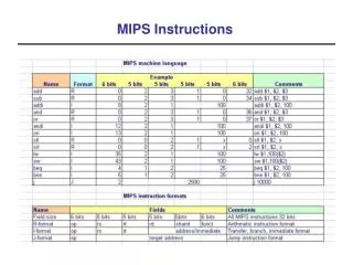
Control • Selecting the operations to perform (ALU, read/write, etc.) • Controlling the flow of data (multiplexor inputs) • Information comes from the 32 bits of the instruction • Example: add $8, $17, $18 Instruction Format: 000000 10001 10010 01000 00000 100000 op rs rt rd shamt funct • ALU's operation based on instruction type and function code
Control • e.g., what should the ALU do with this instruction • Example: lw $1, 100($2) 35 2 1 100 op rs rt 16 bit offset • ALU control input000 AND 001 OR 010 add 110 subtract 111 set-on-less-than • Why is the code for subtract 110 and not 011?
ALUOp computed from instruction type Control • Must describe hardware to compute 3-bit ALU conrol input • given instruction type 00 = lw, sw 01 = beq, 11 = arithmetic • function code for arithmetic • Describe it using a truth table (can turn into gates):
Control • Simple combinational logic (truth tables)
Our Simple Control Structure • All of the logic is combinational • We wait for everything to settle down, and the right thing to be done • ALU might not produce “right answer” right away • we use write signals along with clock to determine when to write • Cycle time determined by length of the longest path We are ignoring some details like setup and hold times
Single Cycle Implementation • Calculate cycle time assuming negligible delays except: • memory (2ns), ALU and adders (2ns), register file access (1ns)
Where we are headed • Single Cycle Problems: • what if we had a more complicated instruction like floating point? • wasteful of area • One Solution: • use a “smaller” cycle time • have different instructions take different numbers of cycles • a “multicycle” datapath:
Multicycle Approach • We will be reusing functional units • ALU used to compute address and to increment PC • Memory used for instruction and data • Our control signals will not be determined soley by instruction • e.g., what should the ALU do for a “subtract” instruction? • We’ll use a finite state machine for control
Review: finite state machines • Finite state machines: • a set of states and • next state function (determined by current state and the input) • output function (determined by current state and possibly input) • We’ll use a Moore machine (output based only on current state)
Multicycle Approach • Break up the instructions into steps, each step takes a cycle • balance the amount of work to be done • restrict each cycle to use only one major functional unit • At the end of a cycle • store values for use in later cycles (easiest thing to do) • introduce additional “internal” registers
Five Execution Steps • Instruction Fetch • Instruction Decode and Register Fetch • Execution, Memory Address Computation, or Branch Completion • Memory Access or R-type instruction completion • Write-back step INSTRUCTIONS TAKE FROM 3 - 5 CYCLES!
Step 1: Instruction Fetch • Use PC to get instruction and put it in the Instruction Register. • Increment the PC by 4 and put the result back in the PC. • Can be described succinctly using RTL "Register-Transfer Language" IR = Memory[PC]; PC = PC + 4;Can we figure out the values of the control signals?What is the advantage of updating the PC now?
Multicycle Approach Instruction Fetch IR = Memory[PC] PC = PC + 4
Step 2: Instruction Decode and Register Fetch • Read registers rs and rt in case we need them • Compute the branch address in case the instruction is a branch • RTL: A = Reg[IR[25-21]]; B = Reg[IR[20-16]]; ALUOut = PC + (sign-extend(IR[15-0]) << 2); • We aren't setting any control lines based on the instruction type (we are busy "decoding" it in our control logic)
Multicycle Approach Instruction Decode and Register Fetch A = Reg[IR[25-21]]; B = Reg[IR[20-16]]; ALUOut = PC + (sign-extend(IR[15-0]) << 2);
Step 3 (instruction dependent) • ALU is performing one of three functions, based on instruction type • Memory Reference: ALUOut = A + sign-extend(IR[15-0]); • R-type: ALUOut = A op B; • Branch: if (A==B) PC = ALUOut;
Multicycle Approach Execute BRANCH R-TYPE Mem REF Execute
Step 4 (R-type or memory-access) • Loads and stores access memory MDR = Memory[ALUOut]; or Memory[ALUOut] = B; • R-type instructions finish Reg[IR[15-11]] = ALUOut;The write actually takes place at the end of the cycle on the edge
Multicycle Approach Memory Access Memory[ALUOut] = B Or MDR = Mem[ALUOut] Reg[IR[15-11]] = ALUOut R-TYPE Memory Access
Write-back step • Reg[IR[20-16]]= MDR; What about all the other instructions?
Multicycle Approach Write Back Reg[IR[20-16]]= MDR Write Back
Simple Questions • How many cycles will it take to execute this code? lw $t2, 0($t3) lw $t3, 4($t3) beq $t2, $t3, Label #assume not add $t5, $t2, $t3 sw $t5, 8($t3)Label: ... • What is going on during the 8th cycle of execution? • In what cycle does the actual addition of $t2 and $t3 takes place?
Implementing the Control • Value of control signals is dependent upon: • what instruction is being executed • which step is being performed • Use the information we’ve acculumated to specify a finite state machine • specify the finite state machine graphically, or • use microprogramming • Implementation can be derived from specification
Graphical Specification of FSM • How many state bits will we need?
The Big Picture Zilog Z80 Block Diagram MIPS Block Diagram