Download
1 / 16
350 likes | 1.64k Views
Marine Auxiliary Machinery. Chapter 9 Lesson 3 Deck Machinery Anchor Handling. By Professor Zhao Zai Li 05.2006. ANCHOR HANDLING (1). The efficient working of the anchor windlass is essential to the safety of the ship, An anchor windlass can expect to fulfill the following :

E N D
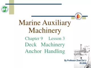
Marine Auxiliary Machinery Chapter 9 Lesson 3 Deck Machinery Anchor Handling By Professor Zhao Zai Li 05.2006
ANCHOR HANDLING (1) • The efficient working of the anchor windlass is essential to the safety of the ship, An anchor windlass can expect to fulfill the following: • 1. The windlass cablelifter brakes must be able to control the running anchor and cable when the cablelifter is disconnected from the gearing during ‘letting go’. Average cable speeds vary between 5-7 m/sec during this operation.
ANCHOR HANDLING (2) • 2. The windlass must be able to heave a certain weight of cable at a specified speed. • This ‘fullload’ duty of the windlass varies (it may be as high as 70 tonne; figures between 20 and 40 tonne are not unusual) but is commonly between 4 and 6 times the weight of one anchor,the speed of haul being at least 9 m/min and up to 15 m/min. • 3. The braking effort obtained at the cable lifter must be at least equal to 40 per cent of the breaking strength of the cable.
ANCHOR HANDLING (3) • Most anchor handling equipment incorporates warpends for mooring purposes and light line Speeds of up to 0.75 to 1.00 m/sec are required. • The most conventional types of equipment in use are as follows.
Mooring windlasses (1) • This equipment is self contained and normally one prime mover drives two cablelifters and two warpends, the latter may not be declutchable and if so, rotate when the cablelifters are engaged. • There is some variation in detail design of cable lifters and in their drives. • Figure 9.5 shows a typical arrangement. • Due to the low speed of rotation required of the cablelifter whilst heaving anchor, (3~5 rev/min) a high gear reduction is needed when the windlass is driven by a high speed electric or hydraulic motor.
Mooring windlasses (2) • This is generally obtained by using a high ratio worm gear followed by a single step of spur gears between the warpend shaft and cablelifters, typically as shown in Figure 9.6. • Alternatively, multi steps of spur gears are used.
Figure 9.5 Part plan of windlass dog-clutch-type lifter
Figure 9.6 Typical electrically driven mooing windlass
Anchor capstans (1) • With this type of equipment the driving machinery is situated below deck and the cablelifters are mounted horizontally being driven by vertical shafts as shown in Figure 9.7. shaft. Anchor cable andwarping capstan
Anchor capstans (2) • In this example a capstan barrel is shown mounted above the cablelifter (not shown) although with larger equipment (above 76 mm dia cable) it is usual to have only the cablelifter, the capstan barrel being mounted on a separate
Winch windlasses • This arrangement utilises a forward mooring winch to drive a windlass unit thus reducing the number of prime movers required. • The port and starboard units are normally interconnected, both mechanically and for power, in order to provide standby drive and to utilise the power of both winches on the windlass should this be required.
Control of windlasses (1) • As windlasses are required for intermittent duty only, gearing is designed with an adequate margin on strength rather than wear. • Slipping clutches are commonly fitted between the prime mover and gearing to avoid the inertia o f the prime mover being transmitted to the machinery in the event of shock loading on the cable when, for example,the anchor is being housed (see Figure 9.8).
Figure 9.8 Slipping clutch
Control of windlasses (2) • Windlasses are normally controlled from a local position , the operator manually applying the cablelifter brake as required to control the speed of the running cable, and whilst heaving anchor the to operator is positioned at the windlass or at the shipside so that he can see the anchor for housing purposes. • It is quite feasible, however, to control all functions of the windlass from a remote position.
Control of windlasses (3) • The spring applied cablelifter brakes are hydraulically released and to aid the operator, the running cable speed and the length paid out are indicated at the remote position during letting go. • The cablelifter can also be engaged from the remote position so that the anchor can be veered out to the waterline before 1etting go or heaved in as required.
Control of windlasses (4) • The windlass is in the most vulnerable position so far as exposure to the elements is concerned and maintenance demands should be an absolute minimum. • Normally primary gearing is enclosed and splash lubricated, maintenance being limited to pressure grease points for gunmetal sleeve bearings. • However, due to the large size of the final of bevel or spur reduction gears, and the clutching arrangements required, these gears are often of the open type and are lubricated with open gear compounds.