Download
1 / 26
270 likes | 452 Views
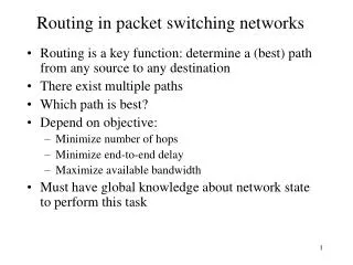
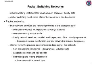
Leon: Chapter 7: Packet-Switching Networks. We skip Chapter 6, because this material is covered in the LAN course. 7.1 Network Services and Internal Network Operation 7.2 Packet Network Topology 7.3 Datagrams and Virtual Circuits 7.4 Routing in Packet Networks 7.5 Shortest Path Algorithms

E N D
Leon: Chapter 7:Packet-Switching Networks We skip Chapter 6, because this material is covered in the LAN course
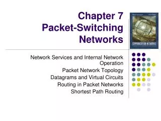
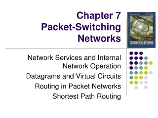
7.1 Network Services and Internal Network Operation 7.2 Packet Network Topology 7.3 Datagrams and Virtual Circuits 7.4 Routing in Packet Networks 7.5 Shortest Path Algorithms 7.6 ATM Networks (Skip) 7.7 Traffic Management and QOS 7.8 Congestion Control C7: Outline
t1 t0 Top level view: a network transfers info among users Network The figure simply shows transmission of a single block or a stream of info Figure 7.1
Peer-Peer Protocols Operating End-to-End Across Networks Messages Messages Segments Transport layer Transport layer Network service Network service Network layer Network layer Network layer Network layer End system b End system a Data link layer Data link layer Data link layer Data link layer Physical layer Physical layer Physical layer Physical layer Protocol Stack View. In C7 we are mostly concerned with the network layer Figure 7.2
3 2 2 3 2 2 2 2 2 2 2 2 1 1 2 2 2 1 1 1 1 1 1 1 2 1 1 1 1 1 3 3 4 Layer 3 Entities work together to provide services to Layer 4 Entities Spatial view C 3 End system b End system a 4 4 3 3 Medium B A Network 1 Physical layer entity Network layer entity Network layer entity Data link layer entity Transport layer entity 2 Figure 7.3
Packet Network Topologies: How do users access a packet-switching network? Network access . . . MUX Node One way is shown. Today the MUX might be a shared DSL or Cable Modem. More likely it would be a router that permits a LAN connection between the PCs. Figure 7.4
Mostly users at one geographic site are connected with one or more Local Area Networks (a) (b) LAN LAN 1 Bridge LAN 2 (a) Broadcasts frames to all PCs. (b) A bridge usually just connects LANs to make a larger broadcast segment, but a LAN switch isolates traffic to a particular LAN, unless it needs to be sent to another LAN Figure 7.5
LANs are connected usually connect by switches or routers to isolate traffic to a particular segment if possible Such a network of LANs is called a campus network The next slide shows a campus network with a backbone internal to the organization It also has a gateway to connect to other networks, usually the Internet A site with remote locations might lease lines or share frame relay interconnections. A multiplexer or router helps share the line by queueing packets to be sent A large site usually sets up many LANs
The s = LAN switch. The S is usually a router Gateway Organization Servers To internet or wide area network s s Backbone R R R S Departmental Server S S R R R s s s s s s s s s Figure 7.6
The campus backbone is usually a high speed LAN FDDI at 100Mbps is common, or Gigabit Ethernet The traffic within an extended LAN segment is delivered using 48-bit physical addresses; however applications use 36-bit IP addresses. The Address Resolution Protocol ARP automatically builds tables to relate the two. To connect the campus network to the larger Internet, we go one more step up the hierarchy. The campus network is then called an autonomous system More about the typical campus network
The autonomous system connects to the rest of the internet via border routers at ISP Points of Presence Interdomain level Border routers Internet service provider Autonomous system or domain Border routers LAN level Intradomain level Figure 7.7
About 20 in US See Russ Haynal page on resources navigators.com/isp.html Some of the largest are bankrupt Connections at NAP and MAEs Role of the National Service Providers
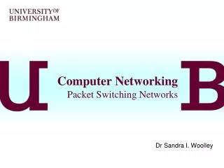
NSPs are connected at Network Access Points National service provider A (a) National service provider B NAP NAP National service provider C (b) NAP RA Details RB Route server LAN RC Figure 7.8
Components of a Generic Switch/Router Control 1 Line Card Line Card 1 2 2 Line Card Line Card Interconnection Fabric 3 3 Line Card Line Card … … … … N N Line Card Line Card Figure 7.10
Building a router from a PC CPU I/O Bus 1 NIC Card 2 NIC Card NIC Card 3 Main Memory … … N NIC Card Figure 7.11
1 1 2 2 N N Routers perform demultiplexing and multiplexing functions … … Figure 7.12
Message switching Message Message Message Subscriber A Message Subscriber B Network nodes Figure 7.13
Delays in Message Switching Source T t Switch 1 t p Switch 2 t t Destination Delay Minimum Delay = 3p + 3T Figure 7.14
Datagram Packet Switching Packet 1 Packet 1 Packet 2 Packet 2 Packet 2 Figure 7.15
Delays in Packet Switching; note that pipelining can speed transfer vs. message switching Source t 1 3 2 p Switch 1 t 3 1 2 p + P Switch 2 t p + P 1 2 3 t Destination L hops 3 hops Lp + (L-1)P first bit received 3p + 2(T/3) first bit received Lp + LP first bit released 3p + 3(T/3) first bit released 3p + 5 (T/3) last bit released Lp + LP + (k-1)P last bit released where T = k P Figure 7.16
Routing table in connectionless packet switching Output port Destination address 0785 7 1345 12 1566 6 2458 12 Figure 7.16
Virtual Circuit Packet Switching Packet Packet A virtual connection is set up for the duration of the call, which simplifies routing. Other streams can use the same physical links, so we still have advantage of sharing resources. Figure 7.17
Delays in virtual-circuit packet switching t Connect request 1 3 2 CC t Release 3 CR 1 2 CC t Connect confirm 1 2 CR 3 t Figure 7.19
Signaling message exchanges in virtual circuit set up Connect request Connect request Connect request SW 1 SW n SW 2 … Connect confirm Connect confirm Figure 7.20
Output port Next identifier Identifier 12 44 13 Entry for packets with identifier 15 15 15 23 27 13 16 58 7 34 Example of a virtual circuit routing table for an input port. ID is virtual circuit number. Abbreviated headers can be used. Figure 7.21
"Cut through" packet switching speeds by starting output transmission as soon as header is decoded Source t 2 1 3 Switch 1 t 2 3 1 Switch 2 t 2 1 3 t Destination Minimum Delay = 3p+T Standard virtual circuits have same delay to send k packets and the datagram variety, plus the set up phase Figure 7.22