Download

1 / 55
560 likes | 697 Views
CS1104 Help Session I Instruction Set Architectures. Colin Tan ctank@comp.nus.edu.sg. Basic Concepts - Instructions. Computers can do wonderful things: Play Quake 3 Arena Watch South Park VCDs Sometimes can do a little bit of work

E N D
CS1104 Help Session IInstruction Set Architectures Colin Tan ctank@comp.nus.edu.sg
Basic Concepts - Instructions • Computers can do wonderful things: • Play Quake 3 Arena • Watch South Park VCDs • Sometimes can do a little bit of work • Unlikely with Windows 95/98 machines, since they crash so often. • Achievable through sophisticated devices like Arithmetic Logic Units, 3D graphics cards etc.
Basic Concepts - Instructions • Despite all the sophistication computers are a little dumb • Computers can do absolutely nothing without being told what to do. • We use “machine instructions” to tell our computers how to achieve these goals • Machine instructions are very basic instructions, much more basic than C, Pascal or Java instructions. • Operates mostly on binary bit patterns directly. No support for characters etc. • Examples: add, sub, mul, div, ror, rol, shl, shr, not, and, or, xor, bne, beq, j, jr
Basic Concepts - Registers • Machine instructions operate on binary data • Data must be kept close to operational units (adders, multipliers, shifters etc). • To do this, we have special storage units called Registers • In the MIPS R2000, registers store 32-bit numbers. • There are a total of 32 such registers: • $zero: Always contains ‘0’, no matter what. • $v0 - $v1: Used to return values from a function • $a0 - $a3: Used to pass arguments to a function • $t0 - $t7: Used to store temporary results • $s0 - $s7: Used to save data
Basic Concepts - Registers • Registers • MIPS Registers (cont’d) • $t8 - $t9: More temporary registers • $gp: Global Pointer (not normally used) • $sp: Stack Pointer (used for more advanced programming) • $fp: Frame Pointer (used for more advanced programming) • $ra: Return Address (used for functions)
Basic Concepts - Memory • Memory • There are very few registers (only 32 in the MIPS R2000). Cannot possibly store all the data that you need in these 32 registers. • There is a much larger pool where both instructions and data are stored, called “memory”. • Think of memory as a huge cabinet with millions of pigeon-holes. • Each pigeon-hole stores data or instructions (what to do with the data).
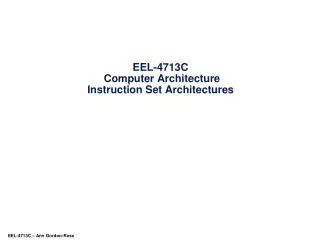
8 data data 7 data 6 data 5 instr 4 3 instr instr 2 instr 1 0 instr Basic Concepts - Memory MEMORY Each pigeon hole stores 8-bits
Basic Concepts - Memory • How do we specify which pigeon hole to put stuff into, and which pigeon hole to take stuff out? • Assign each pigeon hole with an index number, starting with 0 for the lowest pigeon hole, and number sequentially up to the last pigeon hole. • So if we have 32,768 pigeon holes (i.e. “32K of memory”) then the first pigeon hole is 0, the last is 32,767. • These numbers are known as “addresses”. • Some instructions (e.g. lw and sw in MIPS) can specify which address in memory to take data from. • Other MIPS instructions operate only on registers, and do not interact with memory.
3 2 1 0 1C 09 F0 EA Basic Concepts - Endians • Endians specify how a computer stores words (see later) in memory. E.g. take the 32-bit word: EA F0 09 1C (i.e. 1110 1010 1111 0000 0000 1001 0001 1100) • In a big-endian system (MIPS R2000, Sun UltraSparc II), data is stored in memory exactly as shown above: MEMORY
3 2 MEMORY 1 0 EA F0 09 1C Basic Concept - Endians • Little Endian • Data in memory is stored in reverse: • In the older processors (e.g. the Synertek SY6502 used in the Apple II) this made it easier to access large pieces of data. • Newer processors (e.g. the Intel Pentium series) retained this for compatibility reasons.
Basic ConceptsByte and Word Addressing • In the MIPS and most other processor architectures, each pigeon-hole in memory stores 1 byte (i.e. 8 bits of data). So each index number (i.e. address) would point to exactly 8 bits of data. • However, for efficiency reasons, most processors retrieve and store data in the pigeon holes in larger units. • In the MIPS architecture, data/instruction is retrieved and written 4 bytes at a time (i.e. 4 pigeon holes each time). • We call this larger unit a “word”, so each “word” in the MIPS architecture is 4 bytes (32 bits). • Other architectures may have different “word” sizes: • For example, the Digital Alpha 21062 uses 8-byte (64 bit) words. • The older Intel processors (80286 and below) used 2-byte words.
Basic ConceptsByte and Word Addressing • We can hence access data either byte-by-byte (byte addressing) , or word-by-word (word addressing). • In word-addressing, we will retrieve data 1 word (i.e. in MIPS, 4 bytes or 4 pigeon-holes) at a time. • Accessing word 0 will be equivalent to accessing bytes 0, 1, 2 and 3 at one time, accessing word 1 will be equivalent to accessing bytes 4, 5, 6 and 7 etc. • Data and instructions are always loaded 4-bytes at a time.
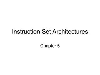
data1 8 7 data0 data0 6 data0 5 data0 4 3 instr0 instr0 2 instr0 1 0 instr0 Basic ConceptsByte and Word Addressing Word 2 (partial) Word 1 Word 0 Byte Addressing Word Addressing
Basic Concepts Word Boundaries • We will assume a MIPS architecture, so each word corresponds to 4 bytes. • Word 0 corresponds to byte address 00000, 00001, 00010, 00011 • Word 1 corresponds to bytes address 00100, 00101, 00110, 00111 • Word 2 corresponds to bytes address 01000, 01001, 01010, 01011 • Word 3 corresponds to bytes address 01100, 01101, 01110, 01111 etc. • The start of each block of 4 byte words is called the “word boundary”. So boundary of word 0 is byte 00000, boundary of word 1 is byte 00100, word 2 is byte 01000 etc. • Notice that the last 2 bits of each word boundary byte address is always 00. • Hence we can convert a byte address to a word address by dropping the last two bits • Byte adress 00100 • Drop last 2 bits: 001. So byte address 00100 corresponds to word 001.
Basic Concepts Word Alignments • If words (i.e. blocks of 4 bytes) are loaded at word boundaries, this is known as an “aligned load”. • E.g. loaded from byte address 4 onwards, bytes at address 4, 5, 6 and 7 will be loaded. • If words are loaded from the middle of a word this is an “unaligned load”. • E.g. if we started loading from byte 6, then bytes 6 and 7 of word 1 are loaded, followed by bytes 8 and 9 from word 2. • Unaligned loading of data decreases performance as 2 loads are required to load 1 word of data • Unaligned loading of instructions causes programs to crash.
Opcodes, Operands etc. • Example Instruction: • add $s1, $t1, $t2 • Takes the contents of register $t1 and $t2 (remember that they store binary numbers), add them together, and store the sum into register $s1. • $t1, $t2 tell the computer what to add, and $s1 tells the computer where to store the results to. We call these specifics “operands”. • “add” tells the computer what exactly to do with $t1, $t2 and $s1. We call this the “operation”. • Computers understand only binary numbers, and we must represent “add” as a binary number (e.g. 010110). We call this binary representation the “operation code”, or “opcode” for short.
Instruction Formats • The operands must likewise be expressed in binary: • Registers in MIPS are expressed in 5-bit numbers 00000 ($zero) to 11111 ($ra). • The binary patterns for the opcode, operands and other information stuck together into a single binary number called an “instruction”. • How exactly we stick these parts together is called the “instruction format”.
opcode rs rt rd shamt fn Instruction Formats • Example: R Mode instruction in MIPS • rs, rt and rd specify the source ($t1, $t2) and destination registers ($s1) • shamt: “Shift Amount” used for bit-shift operations like shl, shr, ror and rol • fn: Used to specify arithmetic operations (add, subtract etc), as all arithmetic operations have a common opcode of 000000.
Instruction Set Architectures • The Instruction Set Architecture (ISA) of a processor specify: • The operations supported (e.g. add, divide, shift bits left, etc.) • The size and types of data to be operated on (e.g. registers, constants, memory data, floating point numbers) • The methods of accessing and operating on data (direct, immediate, displacement, register indirect etc.) • These methods are known as “Addressing Modes” • The format of each instruction • How many operands can an instruction take? • How long should each instruction be?
Instruction Set Architectures • The Instruction Set Architecture is the design of how data should look like and how instructions should behave: • How data should look like: • Integers should be 32 bits long, and they should be 2’s complement. • Floating point numbers should have 1 sign bit, 12 exponent bits and 19 mantissa bits. • How instructions should behave: • Immediate instructions add a constant value to a register and stores the results in another (possibly same) register. • Conditional branches should test certain conditions and jump to a new instruction if necessary. • The ISA is NOT stored in the system, but is used to guide the design of the entire processor.
Addressing Modes • Register mode: • All values to be operated upon come from registers. • E.g. add $3, $1, $2 => $3 = $1 + $2 • Immediate mode: • Add the contents of a register with a constant value: • E.g. addi $3, $1, 128 => $3 = $1 + 128 • Displacement mode: • Take the contents of a register and add it to a constant value. Use this result as a memory address, and fetch data from the memory location indexed by this address: • E.g. sub $3, $1, 64($4) => Addr = $4 + 64, $3 = $1 - mem[Addr]
Addressing Modes • Register Indirect: • Similar to displacement mode, but no constant value is used: • e.g. mul $3, $1, ($2) => addr = $2, $3 = $1 x mem[addr] • Indexed/Base: • Similar to displacement mode, but address is derived by adding the contents of two registers: • e.g. lw $4, ($1 + $2) => addr = $1+$2, $4 = mem[addr] • Direct: • The address of the data is specified directly in the instruction: • e.g. div $2, $1, (1001) => $2 = $1/mem[1001]
Addressing Modes • Memory Indirect: • A register contains an address, and the contents of the pigeon-hole indexed by this address is yet another address, and this other address contains the actual data • add $3, $1, @($2) • addr1 = mem[$2] • addr2 = mem[addr1] • $3 = $1 + mem[addr2] • Very useful for certain operations. • The MIPS R2000 uses only register (R-Mode), immediate and displacement addressing modes (I-Mode). The MIPS has a 3rd addressing mode known as J-Mode.
Instruction Lengths • Some machines use fix-length instructions: • E.g. In the MIPS R2000, ALL instructions are 32 bits long. • This simplifies the processor design, allowing processors to run faster. • Some machines use variable-length instructions: • Each instruction may have a different length. • The shortest VAX (an old processor) instruction is 6 bits, while the longest is over 128 bits. • The length of an instruction is determined by its opcode. • Complex, but allows more flexible ISA design, and better memory utilization.
Instruction Lengths • Some machines have a group of instructions that are of length L1, a second group of length L2 etc. • E.g. Arithmetic instructions are 32 bits, bit-wise instructions are 37 bits etc. • These are “hybrid” machines, since they don’t quite have fixed-length instructions, yet the length of instructions don’t vary as much as machines with variable-length instructions.
Designing Instruction Sets using Expanding Opcodes • We will now look at how to design the design set of a machine using expanding opcodes. • We always make some assumptions: • There are several classes (usually 3, possibly more) of instructions, each requiring different number of operands. • Parts of instructions not used for operands can be converted for use as opcodes instead, giving us a larger range of opcodes. • This practice is known as “expanding opcodes”. • For our exercises, the instructions are usually fixed length (too difficult to design variable length instructions.)
Expanding Opcodes • Take question A4 of assignment 4 for example: • Instructions are 12 bits in length • There are 3 classes of instructions: • I: Instructions with 2 addresses • J: Instructions with 1 address • K: Instructions with no addresses • Class J has 1 address operand fewer than class K, and so we can use one of the address operands as an opcode instead. • Likewise class K has no address operands. So we can use both address operands of class I as opcodes instead.
Class I Class J Class K opcode1 (4) opcode1 (4) opcode1 (4) address 1 (4) opcode2 (4) opcode2 (4) address 2 (4) address 1 (4) opcode3 (4) Expanding Opcodes • Now we have a problem: Since various parts of an instruction can at some times be operands, and at other times opcodes, how do we tell the difference? • This is important: Operands tell us where to get data to operate on. Opcodes tell us what to do! • They are fundamentally different, and it is important for the processor to know how to treat parts of an instruction. • Won’t do for a processor to try to obey an operand, or try to add opcodes. We’ll get nonsensical results!
Expanding Opcodes • The trick is to reserve bit patterns to differentiate between the classes of instructions. • If the processor knows which class an instruction belongs to, then it will know whether a particular part of an instruction is operand or opcode.
Expanding Opcodes An Example • A particular processor has 16 bit instructions divided into 3 classes. Addresses on this machine are 4 bits long, and registers are 3 bits. • 31 instructions in class I operate on 2 addresses and 1 register • 12 instructions in class J operate on 1 address and 1 register • 22 instructions in class K operate on 1 register only.
Class K Class J Class I opcode1 (5) opcode1 (5) opcode1 (5) addr1 (4) opcode2 (4) opcode2 (4) addr1 (4) opcode3 (4) addr2 (4) reg (3) reg (3) reg (3) Expanding OpcodesAn Example • To start-off the design, it is easier to start designing the instruction with the most number of opcode bits. This would be class I (numbers in brackets indicate length of each portion in bits) • For class J instructions, we only need 1 address. So we convert addr1 to an opcode instead. Likewise class K instructions only require the reg field, and we can convert the addr2 field into another opcode (opcode3) field.
Class I 00000 to 11110 addr1 addr2 reg Expanding OpcodesAn Example • Now we start deciding on the range of values our opcodes (opcode1, opcode2 and opcode3) can take: • We need 31 class I instructions. We also need to differentiate between class I and other classes so that the processor knows whether to treat the following part of the instruction as operand (for class I) or opcode (for classes J and K). • We assign opcode1 to be from 00000 to 11110 for the 31 instructions in class I. We reserve the value 11111 to differentiate class I from J and K. That is, if opcode1 = 11111, we know that this is NOT a class I instruction.
Class J 11111 0000 to 1011 addr2 (4) reg (3) Expanding OpcodesAn Example • For class J, opcode1 must be 11111 (otherwise the processor will assume that this is a class I instruction). We need 12 opcode2 values, so we just take 0000 to 1100. • For class K, opcode1 must be 11111 (otherwise the processor will assume that this is a class I instruction). Opcode2 cannot take any value between 0000 and 1011, as these are reserved for class J. • At the same time, we don’t have enough opcode3 bits to fully encode all 22 class K instructions!
Class K 11111 11111 1100 1101 0000 to 1111 0000 to 0101 reg (3) Expanding OpcodesAn Example • We can use an opcode2 value of 1100 and opcode3 values between 0000 and 1111 to encode the first 16 class K instructions. • We then use an opcode value of 1101 and opcode3 values between 0000 and 0101 to encode the remaining 6 class K instructions:
Assignment 4Question A4 • Question A4: • Instructions are 12 bits in length • There are 3 classes of instructions: • I: Instructions with 2 addresses • J: Instructions with 1 address • K: Instructions with no addresses • Questions: • a) Find the maximum number of instructions in class J • b) Find the maximum number of instructions in class K • c) Find the minimum total number of instructions • d) Find the maximum total number of instructions
opcode1 address 1 address 2 Assignment 4Question A4 • Maximum number of instructions in Class J • To do this, we need to minimize the number of class J and K instructions. • Since we must have at least one instruction in each class (or the class will cease to exist!), the minimum for class J and K is 1. • We start by drawing out the format of the most number of operands. This will give us a starting point to design the remaining classes. The format of class I instructions is shown here:
Class I opcode1 (4) address 1 (4) address 2 (4) Assignment 4Question A4 • Now we figure out how many bits should be allocated to each part of the instructions. • Each address is 4 bits. Two addresses take up 8 bits. • Overall instruction length is 12 bits. That leaves 4 bits for the opcode opcode1. • In the diagram below the length of each portion is shown in brackets.
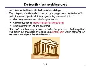
Class I Class J Class K opcode1 (4) opcode1 (4) opcode1 (4) address 1 (4) opcode2 (4) opcode2 (4) address 2 (4) address 1 (4) opcode3 (4) Assignment 4Question A4 • Based on this, we can now work out the format for class J and K instructions: • Class J requires 1 address, so address1 of class I can now be part of the opcode. • Class K requires 0 addresses, so address1 and address2 of class I can now be part of the opcode (i.e. the entire instruction consists only of opcodes.
Class I 0000 address 1 (4) address 2 (4) Assignment 4Question A4 • Having done this, we can now work out the first question: What is the maximum number of class J instructions? • Minimum number of class I and K instructions is 1. • Each opcode1 pattern corresponds to 1 instruction. So we allocate a single bit pattern for class I instructions: 0000 • We can now likewise allocate a single bit pattern for class K instructions: • opcode1 must not be 0000, as this is reserved for class I instructions • opcode2 and opcode3 must have a single bit pattern to identify the one class K instruction.
Class K 0001 0000 0000 Assignment 4Question A4 • Now we can design our class J instruction: • Bit pattern for opcode1 cannot be 0000, as this is reserved for class I instructions. • If bit pattern for opcode1 is 0001, bit pattern for opcode2 cannot be 0000, as this will mislead the processor into thinking that this is a class K instruction (i.e. it will mistake address1 for an opcode instead of an address. • This gives us 2 possibilities:
Assignment 4Question A4 • Two possibilities • opcode1 is 0001 • Value of opcode2 is anything except 0000, i.e. 0001 to 1111. This gives us 15 possible values • opcode1 is 0010 to 1111 • This gives us 14 possible values for opcode1 • Value of opcode2 is anything from 0000 to 1111, giving us 16 possible values for opcode2. • Total number of possible values is 16 x 14 • The max. number of class J instructions is equal the sum of the total number of opcode values for both possibilities: • Max number of class J instructions: 14 x 16 + 15 = 239 instr.
Class I Class J 0000 0001 address 1 (4) 0000 address 2 (4) address 1 (4) Assignment 4Question A4 • Now to determine the maximum number of class K instructions: • We need to minimize the number of class I and J instructions. • This works out to be 1 instruction each. So we need 1 bit pattern for opcode1 reserved for class I. We reserve 0000 • Opcode1 value of 0000 cannot be used for class J. So we use 0001. Also we reserve an opcode2 value of 0000 for class J:
Assignment 4Question A4 • Now we figure out the maximum number of instructions in class K: • opcode1 cannot take a value of 0000, as this is reserved for class I. • opcode1 CAN take a value of 0001, but in this case opcode2 MUST NOT take a value of 0000, as [0001][0000] is reserved for class J. • opcode3 can take any value between 0000 and 1111.
Assignment 4Question A4 • Possibility 1: • opcode1 takes value of 0001: • opcode2 can take any value from 0001 to 1111, giving 15 possible opcode2 values. • opcode3 can take any value from 0000 to 1111, giving 16 possible values. • Total number of opcode2,opcode3 values is 15 x 16 values. • Possibility 2: • opcode1 takes a value of between 0010 and 1111 • This gives 14 possible opcode1 values • opcode2 can take values from 0000 to 1111, giving 16 values. • opcode3 can take values from 0000 to 1111, giving 16 values. • Total number of opcode1,opcode2,opcode3 values is 14 x 16 x 16
Assignment 4Question A4 • The max number of class K instructions is the sum of the total number of opcode values for both possibilities: • max number of class K instructions = 15 x 16 + 14 x 16 x 16 =3,824 opcodes
Assignment 4Question A4 • Now we answer the third question: What is the minimum total number of instructions, assuming that the encoding space of the instruction is fully utilized. • “Encoding space fully utilized” simply means that we can no longer encode anymore instructions. • This implies that every class of instructions is encoded to the maximum (i.e. we maximize every single instruction class). • To find the minimum total number of instructions, we maximize every class of instructions starting from the smallest class to the largest. • Which is the smallest class? • Which is second smallest? • Which is largest?
Class I 0000 to 1110 address 1 (4) address 2 (4) Assignment 4Question A4 • The maximum number of instructions is proportional to the number of opcode bits. • So the smallest class of instructions is class I, which has 4 opcode bits. • To maximize the number of class I instructions: • We need to set aside one bit pattern for opcode1 to indicate instructions that are NOT in class I. We set aside 1111. So we have a range of opcode1 values from 0000 to 1110. • This gives us 15 possible opcode1 values, giving us 15 class I instructions.
Class J 1111 0000 to 1110 address 1 (4) Assignment 4Question A4 • The next smallest set of instructions is class J, which has a total of 8 opcode bits (4 opcode1 and 4 opcode2 bits). opcode1 must take a value of 1111 (otherwise the instruction is a class I instruction). • For opcode2, we now need to set aside 1 bit pattern to differentiate out instructions that are NOT in class J. We choose 1111. So opcode2 can take a value from 0000 to 1110, giving 15 possible opcode2 values. Hence class J will have 15 instructions:
Class K 1111 1111 0000 to 1111 Assignment 4Question A4 • Now we maximize class K. opcode1 must take a value of 1111 (other bit patterns 0000 to 1110 for opcode1 belong to class I), and opcode2 must take a value of 1111 (other bit patterns 0000 to 1110 for opcode2 belong to class J). • opcode3 can take any value from 0000 to 1111, since we no longer need to reserve values to differentiate out other classes of instructions, giving us 16 opcode3 values. Hence we can have 16 class K instructions.
Assignment 4Question A4 • The total number of possible opcodes for all 3 classes will give us the minimum total number of instructions: • # of class I opcodes: 15 • # of class J opcodes: 15 • # of class K opcodes: 16 • This gives us a total of 46 opcodes, or 46 instructions.