BPM design
Discover various BPM types such as electrostatic, resistive, inductive, and more. Learn about measurements, requirements, and conclusions. Delve into electrode configurations, frequency responses, and design considerations explored at the FP420 BPM Workshop by Lars Søby from CERN.

BPM design
E N D
Presentation Transcript
BPM design • Introduction • BPM types • Bench measurements • Other requirements • Conclusion BPM design - FP 420 BPM Workshop - Lars Søby (CERN)
+ + Introduction E-Field TEM Wave 1/(bg) Static Point Charge Relativistic Point Charge Image current distribution BPM design - FP 420 BPM Workshop - Lars Søby (CERN)
Different BPM types } • Electrostatic • Button • Electromagnetic coupler • Resistive • Inductive • Cavity • Re-entrant cavity } Image current } } HOM HF electron beams BPM design - FP 420 BPM Workshop - Lars Søby (CERN)
Electrostatic shoebox BPM Linear cut through a shoebox Beam UR UL Beam • Linear within ¾ of half aperture • Low frequency cutoff (kHz) with high RL • Sensitive to spray particles • Complicated design high cost x Linear Response across the aperture Induced charges carried away by low-impedance circuit or sensed on a high impedance as a voltage BPM design - FP 420 BPM Workshop - Lars Søby (CERN)
Electrostatic BPM Same principle applied to a cylindrical pick-up • The cuts can be made by photo-chemical, sand-blasting or other mechanical means. • Here done by photo-chemical process BPM design - FP 420 BPM Workshop - Lars Søby (CERN)
Ce V to V Ib Zt Rl Button BPM Area A • Lowest longitudinal impedance • Low cost most popular • Non-linear • requires correction algorithm when beam is off-centre • Low frequency cut-off • T = RlCe (few hundreds MHz) • RL =50 ohm, C very small r BPM design - FP 420 BPM Workshop - Lars Søby (CERN)
Frequency domain: Impedance transformers improve the low frequency levels at the expense of the high frequency Time domain: Differentiated pulse Exponential dependence of amplitude on bunch length Button Frequency & Time Response BPM design - FP 420 BPM Workshop - Lars Søby (CERN)
What does a real (LHC) electrostatic button monitor look like? BPM design - FP 420 BPM Workshop - Lars Søby (CERN)
Electromagnetic (Directional) coupler • Four 50Ω lines. • Directional if terminated in both ends • Linear if optimized (φelec≈ 60º) • Higher cost but shorted version is a possible cheaper option. • Narrow band device. BPM design - FP 420 BPM Workshop - Lars Søby (CERN)
+ + + + + EM Stripline Coupler – right travelling beam Up-stream Port Down stream Port Left Right BPM design - FP 420 BPM Workshop - Lars Søby (CERN)
Upstream Downstream • Two termination ports • Upstream: usually used to acquire signal. • Same signal seen whether Downstream port is open, shorted or terminated by Z0 • Downstream: 2 cases • Upstream terminated by Z0 no signal • Upstream short circuit delayed & inverted signal Beam Directivity! Electromagnetic (Directional) coupler a • Is a transmission line (strip line) which couples to the transverse electromagnetic (TEM) beam field Zt = 60 ln[(r+h)/r] Z0*[a/2p(r+h)] • Z0 is the characteristic impedance • a, r, h, l are the mechanical dimensions • t = l/c is the propagation time in the coupler h r BPM design - FP 420 BPM Workshop - Lars Søby (CERN)
Coupler frequency & time response • Sinusoidal amplitude response • Maximum signal for f = 1/4*t • Zero signal for f = 1/2*t • Time domain: • Bipolar pulse BPM design - FP 420 BPM Workshop - Lars Søby (CERN)
Resistive BPM (WCM) • The BEAM current is accompanied by its IMAGE • A voltage proportional to the beam current and the beam position develops on the RESISTORS in the beam pipe gap • The gap must be closed by a box to avoid floating sections of the beam pipe • The box is filled with the FERRITE to force the image current to go over the resistors BPM design - FP 420 BPM Workshop - Lars Søby (CERN)
G.C. Schneider, A 1.5 GHz Wide-Band Beam Position and Intensity Monitor for the Electron-Positron Accumulator (EPA), CERN/PS 87-9 (BT), 1987 A position sensitive WCM is still used in the CERN PS. It contains 96 resistors of 10 in 32 groups of 3 in series), V/IB 1 . Position measurement bandwidth is 9 MHz – 1.5 GHz (2.2 decade) Current measurement bandwidth is 3 MHz – 1.5 GHz (2.7 decade) A Beam Position Sensitive WCM BPM design - FP 420 BPM Workshop - Lars Søby (CERN)
Four or eight electrodes, which covers up to 75 % of the circumference. No feed-thru’s The small electrode diameter step is occupied by a titanium coated ceramic tube. Low longitudinal impedance Small current transformers guides the image currents to an external load. The current transformers (mounted on a PCB) are as small as possible to gain high frequency cut-off with many turns The connection between the electrodes and the cover is made by screws. Inductive Pick-Up LESS RESISTANCE MORE INDUCTANCE BPM design - FP 420 BPM Workshop - Lars Søby (CERN)
IPU – A Low Frequency Model • Electrodes are combined in pairs so that each transformer sees half of the load • Frequency low cut-offs are limited by connection parasitic resistances • Each transformer has one calibration turn (not shown) n=30, RS 7 giving RT 0.1 and RP 4 m fL 150 Hz (RP with L 5 H) fL 10 kHz (RP with L 70 nH) The electrode signal high cut-off frequency is beyond 300 MHz BPM design - FP 420 BPM Workshop - Lars Søby (CERN)
Inductive Pick • The ceramic tube is coated with low resistance titanium layer, resistance:end-to-end 10 , i.e. 15 /square • Primary circuit has to have small parasitic resistances (Cu pieces, CuBe screws, gold plating) • Tight design, potential cavities damped with the ferrite BPM design - FP 420 BPM Workshop - Lars Søby (CERN)
Cavity BPM • Difference of large numbers problem reduced to rejection of the primary fundamental peak. Frequency domain. • Damping time quite high due to intrinsic high Q. → Poor time resolution (~100ns) • Need of extra cavities for orthogonal plane and normalization. • Sub-micron resolution. 18 BPM design - FP 420 BPM Workshop - Lars Søby (CERN)
Re-entrant cavity BPM • Re-entrant geometry for a higher frequency separation between the monopole and dipole modes. → Better CMRR • Resolution: CARE ~ 1um (CALIFES ~5um) • Dynamic range: ± 5mm • Qld = 50 → Time resolution ~ 10ns • ID 78mm; Length ~170mm. BPM design - FP 420 BPM Workshop - Lars Søby (CERN)
Re-entrant cavity BPM electronics BPM design - FP 420 BPM Workshop - Lars Søby (CERN)
C I/2 el. offset B A Bench tests • Position = Kx,y (A-B)/(A+B) + offset = Kx,y *Dx,y /S+ offset • Kx,y = BPM sensitivity estimated from simulations or measured. Linear or polynomial fits can be used. • Offset = Difference between mechanical center and electrical center. For high precision this must be measured using metrology and a stretched wire. • To find the offset with micron precision (with respect to an external reference) move the wire to the electrical center, rotate the BPM 180º, and move the wire the new electrical center. • The difference between the two RELATIVE measurements Is equal to two times the electrical offset D BPM design - FP 420 BPM Workshop - Lars Søby (CERN)
IPU Bench test A thin wire forming a coaxial line was displaced diagonally across the pick-up aperture. The measurement was done with a network analyzer: signal was applied to the wire and hybrid signals were observed. BPM design - FP 420 BPM Workshop - Lars Søby (CERN)
Electrostatic BPM bench measurement D=S=29.2mm Offset = 0.1mm BPM design - FP 420 BPM Workshop - Lars Søby (CERN)
Other requirements • Must be vacuum tight down to 10-9 Torr. • Must be bake able to 150º C. Watch out for stresses due to different thermal expansions, i.e ceramic and metal. • External reference directly connected to the detector or via WPS-system. • Minimize front-end electronics due to radiation. BPM design - FP 420 BPM Workshop - Lars Søby (CERN)
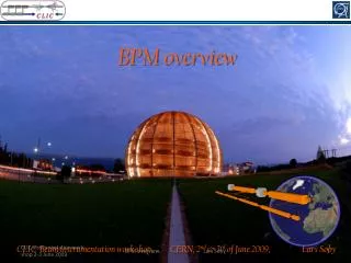
BPM overview BPM design - FP 420 BPM Workshop - Lars Søby (CERN)
Conclusion • To be filled in later…… BPM design - FP 420 BPM Workshop - Lars Søby (CERN)