Floating Point/Multicycle Pipelining in DLX
300 likes | 466 Views
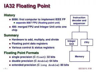
Floating Point/Multicycle Pipelining in DLX. Completion of DLX EX stage floating point arithmetic operations in one or two cycles is impractical since it requires: A much longer CPU clock cycle, and/or An enormous amount of logic.

Floating Point/Multicycle Pipelining in DLX
E N D
Presentation Transcript
Floating Point/Multicycle Pipelining in DLX • Completion of DLX EX stage floating point arithmetic operations in one or two cycles is impractical since it requires: • A much longer CPU clock cycle, and/or • An enormous amount of logic. • Instead, the floating-point pipeline will allow for a longer latency. • Floating-point operations have the same pipeline stages as the integer instructions with the following differences: • The EX cycle may be repeated as many times as needed. • There may be multiple floating-point functional units. • A stall will occur if the instruction to be issued will either causes a structural hazard for the functional unit or cause a data hazard. • The latency of functional units is defined as the number of intervening cycles between an instruction producing the result and the instruction that uses the result. • The initiation or repeat interval is the number of cycles that must elapse between issuing an instruction of a given type.
Extending The DLX Pipeline to Handle Floating-Point Operations: Adding Non-Pipelined Floating Point Units
Extending The DLX Pipeline: Multiple Outstanding Floating Point Operations Latency = 0 Initiation Interval = 1 Latency = 6 Initiation Interval = 1 Pipelined Integer Unit Hazards: RAW, WAW possible WAR Not Possible Structural: Possible Control: Possible Floating Point (FP)/Integer Multiply EX IF ID WB MEM FP Adder FP/Integer Divider Latency = 3 Initiation Interval = 1 Pipelined Latency = 24 Initiation Interval = 25 Non-pipelined
Pipeline Characteristics With FP • Instructions are still processed in-order in IF, ID, EX at the rate of instruction per cycle. • Longer RAW hazard stalls likely due to long FP latencies. • Structural hazards possible due to varying instruction times and FP latencies: • FP unit may not be available; divide in this case. • MEM, WB reached by several instructions simultaneously. • WAW hazards can occur since it is possible for instructions to reach WB out-of-order. • WAR hazards impossible, since register reads occur in-order in ID. • Instructions are allowed to complete out-of-order requiring special measures to enforce precise exceptions.
IF ID M1 M2 M3 M4 M5 M6 M7 WB MULTD MEM CC 10 CC 1 CC 2 CC 3 CC 4 CC 5 CC 6 CC 7 CC 8 CC 9 CC 11 ADDD IF ID A1 A2 A3 A4 WB MEM LD EX WB IF ID MEM IF ID EX WB SD MEM FP Operations Pipeline Timing Example All above instructions are assumed independent
CC 10 CC 1 CC 2 CC 3 CC 4 CC 5 CC 6 CC 7 CC 8 CC 9 CC 11 CC12 CC13 CC14 CC15 CC16 CC17 CC18 IF ID M1 M2 M3 M4 M5 M6 M7 WB MEM IF ID A1 A2 A3 A4 WB MEM IF ID EX WB MEM IF ID EX WB MEM STALL STALL STALL STALL STALL STALL STALL STALL STALL STALL STALL STALL STALL STALL STALL STALL STALL FP Code RAW Hazard Stalls Example(with full data forwarding in place) LD F4, 0(R2) MULTD F0, F4, F6 ADDD F2, F0, F8 SD 0(R2), F2 Third stall due to structural hazard in MEM stage
IF ID M1 M2 M3 M4 M5 M6 M7 WB MEM CC 10 CC 1 CC 2 CC 3 CC 4 CC 5 CC 6 CC 7 CC 8 CC 9 CC 11 IF ID A1 A2 A3 A4 WB MEM EX EX WB WB IF IF ID ID MEM MEM IF IF IF ID ID ID EX EX EX WB WB WB MEM MEM MEM FP Code Structural Hazards Example MULTD F0, F4, F6 . . . (integer) . . . (integer) ADDD F2, F4, F6 . . . (integer) . . . (integer) LD F2, 0(R2)
Maintaining Precise Exceptions in Multicycle Pipelining • In the DLX code segment: DIVF F0, F2, F4 ADDF F10, F10, F8 SUBF F12, F12, F14 • The ADDF, SUBF instructions can complete before DIVF is completed causing out-of-order execution. • If SUBF causes a floating-point arithmetic exception it may prevent DIVF from completing and draining the floating-point may not be possible causing an imprecise exception. • Four approaches have been proposed to remedy this type of situation: • Ignore the problem and settle for imprecise exception. • Buffer the results of the operation until all the operations issues earlier are done. (large buffers, multiplexers, comparators) • A history file keeps track of the original values of registers (CYBER180/190, VAX) • A Future file keeps the newer value of a register; when all earlier instructions have completed the main register file is updated from the future file. On an exception the main register file has the precise values for the interrupted state.
DLX FP SPEC92 Floating Point Stalls Per FP Operation
DLX FP SPEC92 Floating Point Stalls
Pipelining and Exploiting Instruction-Level Parallelism (ILP) • Pipelining increases performance by overlapping the execution of independent instructions. • The CPI of a real-life pipeline is given by: Pipeline CPI = Ideal Pipeline CPI + Structural Stalls + RAW Stalls + WAR Stalls + WAW Stalls + Control Stalls • A basic instruction block is a straight-line code sequence with no branches in, except at the entry point, and no branches out except at the exit point of the sequence . • The amount of parallelism in a basic block is limited by instruction dependence present and size of the basic block. • In typical integer code, dynamic branch frequency is about 15% (average basic block size of 7 instructions).
Increasing Instruction-Level Parallelism • A common way to increase parallelism among instructions is to exploit parallelism among iterations of a loop • (i.e Loop Level Parallelism, LLP). • This is accomplished by unrolling the loop either statically by the compiler, or dynamically by hardware, which increases the size of the basic block present. • In this loop every iteration can overlap with any other iteration. Overlap within each iteration is minimal. for (i=1; i<=1000; i=i+1;) x[i] = x[i] + y[i]; • In vector machines, utilizing vector instructions is an important alternative to exploit loop-level parallelism, • Vector instructions operate on a number of data items. The above loop would require just four such instructions.
DLX Loop Unrolling Example • For the loop: for (i=1; i<=1000; i++) x[i] = x[i] + s; The straightforward DLX assembly code is given by: Loop: LD F0, 0 (R1) ;F0=array element ADDD F4, F0, F2 ;add scalar in F2 SD 0(R1), F4 ;store result SUBI R1, R1, 8 ;decrement pointer 8 bytes BNEZ R1, Loop ;branch R1!=zero
Instruction Producing Result FP ALU Op FP ALU Op Load Double Load Double Instruction Using Result Another FP ALU Op Store Double FP ALU Op Store Double Latency In Clock Cycles 3 2 1 0 DLX FP Latency Assumptions Used In Chapter 4 • All FP units assumed to be pipelined. • The following FP operations latencies are used:
Loop Unrolling Example (continued) • This loop code is executed on the DLX pipeline as follows: No scheduling Clock cycle Loop: LD F0, 0(R1) 1 stall 2 ADDD F4, F0, F2 3 stall 4 stall 5 SD 0 (R1), F4 6 SUBI R1, R1, #8 7 BNEZ R1, Loop 8 stall 9 9 cycles per iteration With delayed branch scheduling (swap SUBI and SD) Loop: LD F0, 0(R1) stall ADDD F4, F0, F2 SUBI R1, R1, #8 BENZ R1, Loop SD 8 (R1), F4 6 cycles per iteration
Three branches and three decrements of R1 are eliminated. Load and store addresses are changed to allow SUBI instructions to be merged. The loop runs in 27 assuming LD takes 2 cycles, each ADDD takes 3 cycles, the branch 2 cycles, other instructions 1 cycle, or 6.8 cycles for each of the four elements. Loop Unrolling Example (continued) • The resulting loop code when four copies of the loop body are unrolled without reuse of registers: No scheduling Loop: LD F0, 0(R1) ADDD F4, F0, F2 SD 0 (R1), F4 ; drop SUBI & BNEZ LD F6, -8(R1) ADDD F8, F6, F2 SD -8 (R1), F8 ; drop SUBI & BNEZ LD F10, -16(R1) ADDD F12, F10, F2 SD -16 (R1), F12 ; drop SUBI & BNEZ LD F14, -24 (R1) ADDD F16, F14, F2 SD -24(R1), F16 SUBI R1, R1, #32 BNEZ R1, Loop
The execution time of the loop has dropped to 14 cycles, or 3.5 clock cycles per element compared to 6.8 before scheduling and 6 when scheduled but unrolled. Unrolling the loop exposed more computation that can be scheduled to minimize stalls. Loop Unrolling Example (continued) When scheduled for DLX Loop: LD F0, 0(R1) LD F6,-8 (R1) LD F10, -16(R1) LD F14, -24(R1) ADDD F4, F0, F2 ADDD F8, F6, F2 ADDD F12, F10, F2 ADDD F16, F14, F2 SD 0(R1), F4 SD -8(R1), F8 SD -16(R1),F12 SUBI R1, R1,#32 BNEZ R1, Loop SD 8(R1), F16;8-32 =-24
Loop Unrolling Requirements • In the loop unrolling example, the following guidelines where followed: • Determine that it was legal to move SD after SUBI and BENZ; find the SD offset. • Determine that unrolling the loop would be useful by finding that the loop iterations where independent. • Use different registers to avoid constraints of using the same registers (WAR, WAW). • Eliminate extra tests and branches and adjust loop maintenance code. • Determine that loads and stores can be interchanged by observing that they are independent from different loops. • Schedule the code, preserving any dependencies needed to give the same result as the original code.
Instruction Dependencies • Determining instruction dependencies is important for pipeline scheduling and to determine the amount of parallelism in the program to be exploited. • If two instructions are parallel , they can be executed simultaneously in the pipeline without causing stalls; assuming the pipeline has sufficient resources. • Instructions that are dependent are not parallel and cannot be reordered. • Instruction dependencies are classified as: • Data dependencies • Name dependencies • Control dependencies
Loop: LD F0, 0 (R1) ; F0=array element ADDD F4, F0, F2 ; add scalar in F2 SD 0 (R1), F4 ; store result Instruction Data Dependencies • An instruction j is data dependent on another instruction i if: • Instruction i produces a result used by instructionj, resulting in a direct RAW hazard, or • Instruction j is data dependent on instruction kand instruction k is data dependent on instruction i which implies a chain of RAW hazard between the two instructions. Example: The arrows indicate data dependencies and point to the dependent instruction which must follow and remain in the original instruction order to ensure correct execution.
Instruction Name Dependencies • A name dependence occurs when two instructions use the same register or memory location, called a name. • No flow of data exist between the instructions involved in the name dependency. • If instruction i precedes instruction j then two types of name dependencies can occur: • An antidependence occurs when j writes to a register or memory location and i reads and instruction i is executed first. This corresponds to a WAR hazard. • An output dependence occurs when instruction i and j write to the same register or memory location resulting in a WAW hazard and instruction execution order must be observed.
Renaming the registers used for each copy of the loop body are renamed, only true dependencies remain: Loop: LD F0, 0 (R1) ADDD F4, F0, F2 SD 0(R1), F4 LD F6, -8 (R1) ADDD F8, F6, F2 SD -8 (R1) F8 LD F10, -16 (R1) ADDD F12, F10, F2 SD -16 (R1), F12 LD F14, -24 (R1) ADDD F16, F14, F2 SD -24(R1), F16 SUBI R1, R1, #32 BENZ R1, Loop In the unrolled loop, using the same registers results in name (green) and data tendencies (red) Loop: LD F0, 0 (R1) ADDD F4, F0, F2 SD 0(R1), F4 LD F0, -8 (R1) ADDD F4, F0, F2 SD -8 (R1) F4 LD F0, -16 (R1) ADDD F4, F0, F2 SD -16 (R1), F4 LD F0, -24 (R1) ADDD F4, F0, F2 SD -24(R1), F4 SUBI R1, R1, #32 BENZ R1, Loop Name Dependence Example
if p1 { S1; }; If p2 { S2; } S1 is control dependent on p1 S2 is control dependent on p2 but not on p1 Control Dependencies • Determines the ordering of an instruction with respect to a branch instruction. • Every instruction except in the first basic block of the program is control dependent on some set of branches. • An instruction which is control dependent on a branch cannot be moved before the branch. • An instruction which is not control dependent on the branch cannot be moved so that its execution is controlled by the branch (in the then portion) • It’s possible in some cases to violate these constraints and still have correct execution. • Example of control dependence in the then part of an if statement:
Control Dependence Example Loop: LD F0, 0 (R1) ADDD F4, F0, F2 SD 0 (R1), F4 SUBI R1, R1, #8 BEQZ R1, exit LD F6, 0 (R1) ADDD F8, F6, F2 SD 0 (R1), F8 SUBI R1, R1, #8 BEQZ R1, exit LD F10, 0 (R1) ADDD F12, F10, F2 SD 0 (R1), F12 SUBI R1, R1, #8 BEQZ R1, exit LD F14, 0 (R1) ADDD F16, F14, F2 SD 0 (R1), F16 SUBI R1, R1, #8 BNEZ R1, Loop exit: The unrolled loop code with the branches still in place is shown here. Branch conditions are complemented here to allow the fall-through to execute another loop. BEQZ instructions prevent the overlapping of iterations for scheduling optimizations. Moving the instructions requires a change in the control dependencies present. Removing the branches changes the control dependencies present and makes optimizations possible.
Loop-Level Parallelism (LLP) Analysis • LLP analysis is normally done at the source level or close to it since assembly language and target machine code generation introduces a loop-carried dependence, in the registers used for addressing and incrementing. • Instruction level parallelism (ILP) analysis is usually done when instructions are generated by the compiler. • Analysis focuses on whether data accesses in later iterations are data dependent on data values produced in earlier iterations. e.g. in for (i=1; i<=1000; i++) x[i] = x[i] + s; the computation in each iteration is independent of the previous iterations and the loop is thus parallel. The use of X[i] twice is within a single iteration.
LLP Analysis Examples • In the loop: for (i=1; i<=100; i=i+1) { A[i+1] = A[i] + C[i]; /* S1 */ B[i+1] = B[i] + A[i+1];} /* S2 */ } • S1 uses a value computed in an earlier iteration, since iteration i computes A[i+1] read in iteration i+1 (loop-carried dependence, prevents parallelism). • S2 uses the value A[i+1], computed by S1 in the same iteration (not loop-carried dependence).
LLP Analysis Examples • In the loop: for (i=1; i<=100; i=i+1) { A[i] = A[i] + B[i]; /* S1 */ B[i+1] = C[i] + D[i]; /* S2 */ } • S1 uses a value computed by S2 in a previous iteration (loop-carried dependence) • This dependence is not circular (neither statement depend on itself; S1 depends on S2 but S2 does not depend on S1. • Can be made parallel by replacing the code with the following: A[1] = A[1] + B[1]; for (i=1; ii<=99; i=i+1) { B[i+1] = C[i] + D[i]; A[i+1] = A[i+1] + B[i+1]; } B[101] = C[100] + D[100];
A[1] = A[1] + B[1]; B[2] = C[1] + D[1]; A[99] = A[99] + B[99]; B[100] = C[99] + D[99]; A[2] = A[2] + B[2]; B[3] = C[2] + D[2]; A[100] = A[100] + B[100]; B[101] = C[100] + D[100]; LLP Analysis Example for (i=1; i<=100; i=i+1) { A[i] = A[i] + B[i]; /* S1 */ B[i+1] = C[i] + D[i]; /* S2 */ } Original Loop: Iteration 99 Iteration 100 Iteration 1 Iteration 2 . . . . . . . . . . . . Loop-carried Dependence • A[1] = A[1] + B[1]; • for (i=1; i<=99; i=i+1) { • B[i+1] = C[i] + D[i]; • A[i+1] = A[i+1] + B[i+1]; • } • B[101] = C[100] + D[100]; Modified Parallel Loop: Iteration 98 Iteration 99 . . . . Iteration 1 Loop Start-up code A[1] = A[1] + B[1]; B[2] = C[1] + D[1]; A[99] = A[99] + B[99]; B[100] = C[99] + D[99]; A[2] = A[2] + B[2]; B[3] = C[2] + D[2]; A[100] = A[100] + B[100]; B[101] = C[100] + D[100]; Not Loop Carried Dependence Loop Completion code