Download
1 / 12
120 likes | 235 Views
This outline presents a comprehensive overview of a new electron gun designed to produce a wide, uniform electron beam with specific focus on properties such as total current and cross-section distribution. Central to the development are the external and internal components, including a Hamamatsu Xenon lamp and a palladium photocathode, ensuring energy up to 10 keV and strict beam parallelism. The calibration plan details both simulated and measured responses across elevation and azimuth, emphasizing precise calibration control for various sensor positions and beam characteristics.

E N D
SWEA MAVEN Calibration Plan A. Fedorov
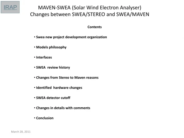
Outline: • New electron gun presentation. • Electron beam properties • Another calibration facilities and control system • What and how to measure
Overview of the new e- gun The goal: To create a wide uniform e- beam as close to the sensor as possible. The total current of the beam and its cross-section distribution should be measured.
Overview of the new e- gun: external parts Hamamatsu Xenon lamp on the movable support Fused silica window
Overview of the new e- gun: internal parts Palladium photocathode and an acceleration system: 1. Energy up to 10keV 2. Strictly parallel e- beam 3. No disturbed e- trajectories at the beam perifery
Overview of the new e- gun: internal parts The photocathode at the end of the light tube. The beam current monitor. The beam monitor on the Y-Z axis stage. 1. Beam cross-section 2. Beam parallelism 3. Beam energy distribution
Overview of the new e- gun: beam cross-section Flux distribution for close lamp position. 20% of variation within 40mm circle. We know the absolute beam for each sensor position
Sensor positioning Y: 0.1mm Elevation (Thet) : +/- 90 deg, 0.1deg Azimuth (Phi) : +/- 170 deg, 0.1deg
Calibration plan: Main Variables Simulated (left) and measured (right) Elevation-K response For D = 0 Simulated (left) and measured (right) Elevation-K response For D = -0.59 K = E/Uan D = Udef/E Elevation, deg (mechanical) Virtual Elevation Azimuth, deg
Calibration plan: Elevation-D profile GF determination 1. Define D – Elevation profile 2. For Az = const, for Elevations (step = 3 deg) : K-D response 3. Calculate dGF/dAz for this point (each anode)
Calibration plan: GF azimuth profile Repeat the same for all Az (step = 2 deg) and all anodes