Download
1 / 22
220 likes | 239 Views
Explore the evolution of the Solar Wind Electron Analyser (SWEA) from Stereo to Maven, highlighting hardware changes, project development, and organization. Learn about critical modifications, sensor interfaces, and historical review insights.

E N D
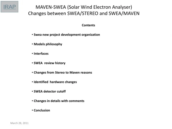
MAVEN-SWEA (Solar Wind Electron Analyser)Changes between SWEA/STEREO and SWEA/MAVEN Contents Swea new projectdevelopmentorganization Modelsphilosophy Interfaces SWEA reviewhistory Changes fromStereo to Mavenreasons Identified hardware changes SWEA detector cutoff Changes in detailswithcomments Conclusion
SWEA project development organization March 28, 2011
Models philosophy Stereo: Two engineering test units (one delivered to SSL) Two flight models Spare parts (not assembled) Maven: One engineering unit Stereo upgraded (not delivered) One flight model Spare parts (not assembled) March 28, 2011
Interfaces Sensor head Mechanical interface with SSL digital electronics part (same as Stereo) Purging tube going through holes to the MCPs via the PCBs center (same as Stereo) Electrical connection with the interface board (SSL) with a pigtail connector Glenair Micro-D 51 pins (see ICD for details) Pinlist has been modified to implement redundant pin-puller command circuit (see ICD CESR-IRAP / SSL) March 28, 2011
SWEA REVIEW HISTORY STEREO/ SWEA PDR September 11-12, 2001 Presentation done by Francis COTIN STEREO / SWEA DOOR MECHANISM PEER REVIEW September 25, 2002 in Toulouse STEREO SWEA CDR November 21-22, 2002 Presentation done by Claude AOUSTIN Maven/Swea peer review (pre-PDR) Feb 3-4, 2010 in Toulouse Presentation done by Maven/Swea team March 28, 2011
SWEA HARDWARE CHANGES FROM STEREO TO MAVEN Hardware changes have to be limited as much as possible due to limited man power and funding Several necessary hardware changes on SWEA detector have been identified by SSL and CESR Different mission context Different accomodation and thermal context. Anomalies reported on Stereo/SWEA -> Corrective actions Different specification measurements (science) ICD requirements Parts obsolescence March 28, 2011
March 28, 2011 MAVEN SWEA instrument Pre-CDR Peer Review @ IRAP March 28-29, 2011
Maven-SWEA detector cutoff March 28, 2011
HW change #5 IRAP Redundant actuator circuit to be added Reason: ICD requirement Actuator control wires are routed along grid ribs, through the center of electronic boards down to the interface connector: there is no problem to route 4 additionnal wires . ICD updated . March 28, 2011
HW change #9 IRAP Scallop inner and outer hemisphere and top cap Reason: reduce scattered electrons, avoid MCPs to count Uvs Top cap will be scalloped the same way as hemispheres Both inner & outer hemispheres need scalopping (was only on outer) Round scalopping has been chosen (easier to implement) See A. Fedorov report (Propagation of the secondary electrons along the analyser for different serration types) « Conclusion: the round scalopping on the both hemispheres improves the suppression of the secondary electrons by factor 3 » March 28, 2011
HW change #10 IRAP • Well known process and contractor • Same coating as for Stereo Cu2S Change surface coating on top cap for a more conductive one On Stereo-SWEA , top cap was coated with Nuflon, this coating has been suspected to become more resistive at very low temperature and bring parasit offsets on top cap that could disturb low energy electrons measurements. Conclusion: Copper black Cu2S has been chosen to coat top cap and hemispheres Gold Top cap coating March 28, 2011
HW change #10 IRAP – parts coating overview Green: black copper Cu2S Red: black nickel (non magnetic) External parts may have to withstand high temperature from thrusters during maneuvers External parts must not be affected by atomic oxygens (=> non magnetic black nickel) Most of the time, SWEA is in the SC shadow, so very cold March 28, 2011 MAVEN SWEA instrument Pre-CDR Peer Review @ IRAP March 28-29, 2011
HW change #11 IRAP Change gain on deflectors to provide some head room to the max deflexion voltage (~+10-20%) Provide the ability to optimize the max deflection Comments: On Stereo, HV between 0 and 1500 v was applied on deflectors We should be able to apply 0-2Kv on Maven-SWEA deflectors Most of modifications that take place on HV board are feasible Components derating are still ok. HV transformers have been fabricated taking in account the max deflexion voltage (2kV) and the oscillation frequency (100Khz) March 28, 2011
HW change #12 CESR Reduce exposed areas of insulators (grid washers) Avoid parasit charged areas in field of view Comments: Special care will be taken to visible insulated parts in FOV during fabrication, assembly and tests. SWEA detector mechanical parts have been fabricated with special care taken to minimize exposed insulated parts areas. March 28, 2011
HW change #13 CESR Potential parts obsolescence issues (e.g. LTC1024AMD/883) Reason: Obsolete parts Comments: Some parts such as LTC1024 (opamp) or 54HC4040 (counter) were either obsolete or with too old date code. Both remaining stocks from Stereo have been re-lifed by Hirex (hirex.fr) Reports available. - External visual inspection - Hermeticity test - Electrical measurements at room temperature - DPA on sample March 28, 2011
HW change #14 CESR Potential Amptek A111F QA issues Reason: Failures has been reported on Stereo-SWEA FM amplifier board. Comments: On Stereo, A111F had been purchased with Amptek « Option 1 » screening On SWEA-Maven, same devices have been ordered with Option1+ screening (NASA Goddard Space Flight Center Preferred Parts List (PPL-20), GSFC S-311-P698) - Amptek Option « 1 » screening (Stereo like) - Customer pre-cap visual inspection. - Extended Burn-In to total of 240 H. - Lot qualification (1000 hours Steady State Life Test at 125°C on sample lot) March 28, 2011
HW change #16 IRAP Change A111 to A121 Reason: Improve count rate , brings dead time correstion capability Comments: A121 case is much bigger and heavier than A111, it is not possible to fit 16 devices on the amplifier board, except if they are installed in stand up position and so the mechanical housing has to be re-designed and the three PCBs have to be re-routed This change leads to many hardware modifications . There has been a discussion between CESR and SSL and it has been decided not to change amplifiers: - To avoid many expensive hardware modifications - A111F is a good solution in more than 90% of the cases - The detector transmission has to be taken in account to determine the maximum counts supported by the charge amplifiers March 28, 2011
HW change #18 IRAP Change geometric factor - may be hemisphere diameter Extrem events, alternative to A111 to A121 change Comments: V0 is already an alternative to geometric factor change March 28, 2011
HW change #19 IRAP Metalize back of deflectors Reason: Less exposed insulators Comments: The deflectors are made of Ultem, insulating material with a gold coating The golden layer did not cover the back of deflectors on Stereo, leaving insulated areas able to be charged and potential parasit electic fields. - Deflectors material (Ultem) have been changed to aluminium. This option has led to re-design parts near deflectors (fixed with insulated washers) - Gaps have been designed to take in account new deflection voltages (polarization between zero and 2 Kv). - Main reason to use aluminium instead of ultem is thermal: deflectors may have to support high temperature (600°C) coming from s/c thrusters during maneuvers: Ultem could not withstand so high temperature. - The golden coating both under bottom deflector and on outer sphere external part (see slide #12) reduces thermal coupling between the lower deflector and the analyser. March 28, 2011
HW change #20 & 21 IRAP Change silver epoxy HV capacitors soldering process Reason: HV caps cracked on Stereo – SWEA Comments: - Meeting has been held with Cnes boards assembly expert (T Battault) - Different HV caps welding and fixation have been defined: * Pre-heating of boards and parts at 70-80°C * Place the board on heating table at 70°C * Weld the capacitors in four points with controled solder temperature * Stick the caps with minimum amount of epoxy glue charged with glass balls March 28, 2011
HW change - Parts potentially exposed to radiation dose • LTC1024 op amps shielded with 1mm thick copper pads • Electronic boards aluminium housing made thicker : 2.65mm (weight +70g) March 28, 2011 MAVEN SWEA instrument Pre-CDR Peer Review @ IRAP March 28-29, 2011
CONCLUSION SWEA – MAVEN is mostly very similar to SWEA – STEREO in terms of design, development plan, etc The instrument has been selected and funded by CNES (French space agency) with verylimited funding (same instrument as for Stereo, very limited changes) Several necessary changes have been identified by SSL and CESR/IRAP due to: New scientific requirements New mission profile Anomalies reported on STEREO Instrument improvement Most of changes have been evaluated and have been or can be implemented SSL and CESR/IRAP have discussed and met agreement on a few other changes. March 28, 2011