CHAPTER 3 LEVELING
CHAPTER 3 LEVELING. Definitions. Definitions.

CHAPTER 3 LEVELING
E N D
Presentation Transcript
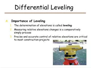
Definitions Definitions • An elevation of a point :The vertical distance between the point and the reference level surface ( datum ) ,the most commonly used datum is the mean sea level (MSL ) . • Leveling :The process by which the elevation of a point above or bellow the MSL or the elevation difference between points is determined, There are several ways to do that: A- Chain surveying: by measuring the slope distance and angle of inclination B- Barometric leveling: by measuring the atmospheric pressure using barometer or an altimeter. C- Trigonometric Leveling: by measuring the horizontal or slope distance between points and the vertical angle ( an elevation or zenith ). D- Differential Leveling: by using an instrument called a level. • Bench Mark ( BM) : well marked points whose elevation has been accurately measured. • Level line: a line perpendicular to the direction of gravity at all points.
Basic Principle of A level A level consists essentially of : a- telescopefor sighting. b- a leveling device to maintain the line of sight a horizontal as Bubble Tube, circular bubble, and some levels use a bubble consists of two separate halves which can be seen through an eyepiece near the telescope. To use the level instrument in making leveling there is a need for : a- Tripod: A three-legged stand used to support a level or other surveying equipments. b- level rods( staff ): used to measure the vertical distance between the points and is usually 3 – 5 m long ( telescopic staff, folding staff, one piece staff ). There three kinds of levels : • The dumpy level: the line of sight ( collimation ) is fixed at right angles to the vertical axis of rotation of the instrument, ( the spirit level attached to the telescope) should also be perpendicular to the vertical axis and parallel to the line of collimation. • The tilting level: the vertical axis is made approximately vertical using circular bubble, and the telescope is leveled horizontal using the telescope spirit level. • The Automatic level: use a system of self-leveling compensators within the optical system of the telescope to bring the line of sight to the horizontal plane.
Line of collimation 0.93 2.56 C B A 0.64 2.97 C A Measuring Elevation Difference using a level The difference in elevation between A & B = the vertical distance AC = RA -RB = 2.56 -0.93 = 1.63 m. ”positive value means Rise” Second reading smaller than first reading represents a rise The difference in elevation between A & B = the vertical distance BC = RA -RB = 0.64 -2.97 = -2.33 m. ”Negative value means Fall” Line of collimation B Second reading greater than first reading represents a fall
Line of collimation 0.93 2.56 C B A 0.64 2.97 C A Line of collimation B Calculation of Unknown Points A- The height of Instrument (collimation ) method: Height of instrument (HI) = Elevation of A + staff reading at A Elevation of B ( RL ) = HI – staff reading at B HI = 520.43 + 0.64 = 521.07 m AMSL RLB= 521.07 – 2.97 = 518.10 m AMSL HI = 520.43 + 2.56 = 522.99 m AMSL RLB = 522.99 – 0.93 = 522.06 AMSL B- The Rise and Fall method: Elevation Difference = first reading at A – second reading at B Elevation of B ( RL ) = elevation of A +Rise or Fall ELev. Diff. = 2.56 – 0.93 = 1.63 m. (Rise) RLB = 520.43 + 1.63 = 522.06 m. AMSL ELev. Diff. = 0.64 – 2.97 = -2.33 m. (Fall) RLB = 520.43 + (-2.33) = 518.10 m. AMSL ∆HAB = HB – HA = RA - RB
Procedure in Differential Level Definitions: 1- Backsight ( BS ): The first reading taken at every instrument station . 2- Foresight ( FS ): The last reading taken at every instrument station . 3- Intermediate sight ( IS ): Any reading taken at an instrument station between BS & FS 4- Turning point ( TP ): A point at which both BS & FS are taken before moving the staff General Procedure: The main purpose is to provide RL for a large number of points, such as the center line of highway, or an area to produce a contour plan, this will be illustrated through the following example of production longitudinal section (profile ) of a road.
Calculations A- The Height of Instrument ( HI ) method: Checks: 1- # of BS reading = # of FS reading = 2 2- ∑BS - ∑FS= RL last point – RL first point(3.450 – 2.231 = 99.979 – 98.760=1.219) 3- ( # of readings = 9 ) = (# of points) + (# of TP) = 8 + 1 4- Sum of all RL excluding the first reduced level = sum of the HI for each setup multiplied by the number of IS and FS readings taken from that setup – sum of IS - sum of FS 689.741= (99.423×4 + 100.625×3 = 699.567) – (∑IS=7.595)–(∑FS =2.231) =689.741
B- The rise and Fall method: Checks: 1- # of BS = # of FS = 2 2-( # of readings = 9 ) = ( # of points = 8 ) + ( # of TP = 1 ) 3- (∑ BS - ∑ FS) = (3.450 – 2.231 ) = 1.219 = (∑ R - ∑ F) = ( 3.079 – 1.860) = 1.219 = ( RL last - RL1st ) = ( 99.979 – 98.760 ) = 1.219
General Notes 1- The accuracy of RL depend on both calculations & correct measurements( staff readings) To ensure accurate elevations of the level points, the field work should start at BM and close at another known BM, or should go back and close at the starting point . 2- If the purpose of leveling is to find out the elevation difference between two points, no intermediate sights are necessary, only BS & FS readings are made. 3- The BS & FS distances should be approximately equal to avoid errors. 4- IF possible staff readings should be made to the nearest mm at TP, and to the nearest cm at other points. 5- TP points should be chosen on firm ground. On soft ground, a special triangular base is used. 6- IF the point whose elevation is to be calculated lie above the level of the sight line like a bridge or a ceiling or top of wall or column, then the staff reading is recorded in negative. 7- If the BM point is the last point, then use the equation ( ∑BS - ∑FS= RL last–RL1st ) to calculate the RL of first point But if the BMlie in the middle of level chain, then calculate the RL of last point ,and after that use the previous equation to calculate the RL of first point and complete the calculations in the normal way.
Example: Using the data in the following figure, calculate the RL of points: A, B, C, D, using both of R & F and HI methods 1- # of BS = # of FS = 2 2- (∑BS - ∑FS)=(-0.67-0.85)=-1.52 & (∑R - ∑F)=(3.38-4.90) = -1.52 & (RLlast – RL1st)=(498.48 – 500.00) = -1.52 3- RL excluding first RL = 501.13 + 503.38 + 498.48 = 1502.99 = (500.6 × 1 + 499.86 × 2 = 1500.32) – (∑FS=0.85) - (∑IS=-3.52) = 1502.99
Uses of Leveling 1- Longitudinal Sections:(center line of a railway, road, canal, sewer or water main) Levels are taken at: 1- every 20m, 50m or 100m depending on the topography (for earthworks computations, A spacing of 20m is common. 2- points at which gradient changes, and at streets intersections. Notes: • Staff readings to 0.01 m accuracy are generally adequate • Common scale for roads works are 1/1000 for horizontal ( Distances ) & 1/100 for vertical ( levels or elevations ). • Points are connected by straight lines on the profile.
2- Cross-Sections: • Some Engineering works require that cross sections be taken at right angles to the center line of a proposed or existing project such as a road. • The width of these of sections are taken 15 m either side of the center for a normal road. • A scale of 1/50 or 1/100 is used for both horizontal and vertical axes.
3- contouring: Definitions: A contour: is an imaginary line connecting points on the ground that have the same elevation. Contour Interval ( CI ): The vertical distance or elevation difference between two successive contours. Contour interval = 20m
Characteristics of Contours 1- Closely contours represent a steep slope, but spaced far contours represent a flat slope. 2-Contours of different values do not cross each other except in a cave, nor do they merge except in a vertically standing surface such as a wall. 3- A single contour can not split into two contours of the same value, and must be a closed circuit not necessary in limits of the contour plan. 4- Irregular contours represent a rough and uneven terrain. 5- contours are perpendicular to the direction of the steepest slope. 6- A hill or depression are represented by closed lines. Factors affecting choice of contour intervals: 1- Contour plan scale: The larger scale is the smaller contour interval. 2- The importance and purpose of a contour plan : for more details, a small contour interval is used. 3- Accuracy, time and cost : For higher accuracy, a smaller interval is used. 4- The topography of the ground : For steep ground a large contour interval is used, but for flat ground a small contour interval is used. 5- The area covered by the plan: For larger areas, a large contour interval is used.
10-20m 10-20m Methods of Contouring 1 2 3 4 5 A B 1- Griding : This method is suitable for flat terrain of small sites ,rectangles or squares of 10 to 20m side are set out on the ground C D E The reduced levels of corners are plotted as a grid on a plan with suitable scale, Then the required contour lines are plotted by a process called linear interpolation. X / 12 = ( 1 / 3 ) X= (1 / 3)×12 = 4m
2-Radiating Lines: Rays are set out on the ground from a central point, and levels are taken along these rays at measured distance from the center, and linear interpolation is used to give the contour lines. 3- Cross-Section Method : In this method, a cross-section are made on a line or a traverse inside the area, levels are taken at points where the topography changes, and linear interpolation is used to give the contour lines.
4- Setting Out Levels: One of the basic applications of leveling is setting out sight rails which enable The excavation operators to cut out earth to an even gradient, and enable the pipe-layer to lay the pipes to this gradient using a boning rod looking The capital letter T with a sight bar across it, the convenient height above Invert would be 3.75 m . Sight rail A, RL= 30.02 + 3.75 =33.77m Distance AB = 60 m Fall = 60 ×( 1 / 100 ) =0.60 m Invert Level at B = 30.02 – 0.60=29.42 m Sight rail at B = 29.42 + 3.75 = 33.17 m If a level is setup nearby has a height Of collimation of 34.85 m, then the staff Reading at A = 34.85 – 33.77 = 1.08 m &Reading at B= 34.85 – 33.17 = 1.68 m
Classes and Accuracy of leveling: The allowable closure error in differential leveling is normally given in the form: ε = ± x √ K mm where: K Is the total leveled distance in kilometers. x = from 10 to 30 for ordinary leveling x = from 2 to 5 for precise leveling Errors in Differential Leveling: 1- Systematic errors: A- Inclination of line of sight due to the earth’s curvature & atmospheric refraction: BC = line of sight refraction from horizontal BD = error due to earth’s curvature CD = Actual error in the staff reading = BD-BC In triangle ABO: (BD + DO)² =AB² + AO² BD² + 2R.BD + R² = L² + R² BD ≈ L² / 2R ≈ 0.0786 L² ( R = 6365 km.) BD in meter & L in km. Refraction = BC ≈ BD/7 ≈0.0786L²/7 CD = 0.0786L² - 0.0786L²/7 = 0.0673L² Where CD is in meter & L is in km When L=1km CD ≈ 0.07m ≈7cm L ≈ 100m ≈0.10km CD ≈.001m ≈1mm
B-Maladjustment of the level collimation Errors: ε 1 = L1.tanα & ε2 = L2.tanα ∆ H = m – n =(a- ε1) – (b- ε2) = ( a – b ) – ( ε1 – ε2 ) =( a – b ) – tanα (L1 – L2) If L1 = L2 ( BS distance = FS) ∆ H = ( a – b ) Due to maladjustment of the level, the line of sight will be actually inclined from the horizontal, this error can be completely eliminated by balancing the BS & FS distances 2-Random errors: the sources of random error are: - The staff not held plumb. - The bubble of the level not perfectly centered. - The incorrect reading of the staff. - The instability of turning points. - Wind 3- Blunders or Mistakes: -Not setting the staff on the same point for a FS and subsequent BS readings. - Recording or Booking of data, like reading 2.58m as 2.85 m or booking a FS in the BS column. - Misreading the staff especially when the marks on the staff are obscured by a tree or fence.
Example TO check a level for the existence of collimation error, the level was set up mid-way between A and B and the following two staff readings were taken:1.92m at A and 1.40m at B. The level was then moved to another position and the readings as in the following figure. Is there a collimation error ? If the answer is yes, then calculate the angle of inclination of the line of sight from the horizontal, as well as correct readings that should have been taken at A & B in the second setup if there was no collimation error? For setup 1: ∆H1 = (correct)=1.92–1.40=0.52m ∆H2 = 1.75 - 1.20 = 0.55 m ∆H1 ≠ ∆H2 there is a collimation error 0.52 =( 1.75 - 1.20 )–tanα(58–23) α = 0º 2’ 57” Correct reading at A (m) = 1.75 – 58 tanα = 1.70 m Correct reading at B (m) = 1.20 – 23 tanα = 1.18 m Check: ∆H = 1.70 – 1.18 = 0.52 m = ∆H1
Reciprocal leveling : 1- Setup the level at point C (first setup a), about 2 to 3 m. from A and take the readings a1 at A and b1 at B ( ∆H1 = a1 – b1 ) 2- Move the level to point D where ( AC = BD ) .Take the readings: a2 at A and b2 at B ( ∆H2 = a2 – b2 ) 3- ∆H =( ∆H1 + ∆H2 ) / 2 =( ( a1 – b1 ) + ( a2 – b2 ) ) / 2 ex: IF RLA = 917.34 m & a1 = 1.44m (BS) & b1 = 1.90m (FS) & a2 = 1.80m (BS) & b2 = 2.34m (FS), what is the elevation of point B? ∆H AB =((1.44 – 1.90) + (1.80 – 2.34)) / 2 = -0.50 m The elevation of B (HB) = HA + ∆H AB = 917.34 + (-0.50) = 916.84 m.
Closure error Closure correction for ∆hi = (- ni / ∑ ni ) × ( ε ) Corrected∆hi = measured ∆hi + closure correction for ∆hi ε(closure error)= h’ ( calculated elevation ) – h ( known elevation ) ni refers to the number of level setups & ∆hi refers to the elevation difference between consecutive stations.