Download

1 / 53
550 likes | 707 Views
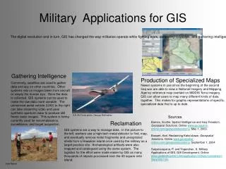
Learn how ArcGIS can revolutionize engineering and surveying industries by customizing tools for design, drafting, field work, topographic mapping, contouring, roadway design, and more. Enhance workflows with specialized commands and automated features tailored for civil engineers and surveyors.

E N D
Engineering Applications employing GIS Technology Engineering Applications employing GIS Technology How ArcGIS can be tailored for Engineering and Surveying Applications Presenter: Aaron Norby Kadrmas, Lee & Jackson
Fields Utilizing GIS Business, Telecommunications, Defense, Health, Homeland Security, Education Oil & Gas, and many more…
Engineers and Surveyors Even Civil Engineers and Surveyors are using GIS, But not to its full extent.
Municipal Clients Civil Engineers and Surveyors working with municipal clients are finding themselves having to supply their clients with data that can be incorporated into the clients’ GIS database
CAD to GIS A CAD file (.dxf, .dwg) has typically been used as the mechanism to transfer the engineer or surveyor’s work to the municipal client
CAD to GIS • The CAD file (.dxf, .dwg) provides: • Exchange of geometric graphics • But not a good mechanism for exchanging attribute data • Attribute data is becoming more and more important for municipal clients
A New Approach Avoid the CAD to GIS transfer by performing the design within the GIS, that is, design with ArcMap !
Design within ArcGIS By creating custom commands and tools, we can utilize ArcGIS as the graphics engine for performing Civil Engineering and Surveying applications
Start to End Approach By creating custom commands and tools, we can utilize ArcGIS to design and draft in a GIS environment "drafting as a by-product of the design process"
Custom Commands/Tools Visual Basic 6 ArcObjects Avenue Wraps Active X DLL’s } Toolbars which can be added to ArcMap, and
Design Processes which can be performed within ArcGIS Survey – Field Work Digital Terrain Model Horizontal Alignments Cross-Sections/Profiles Vertical Alignments Roadway Templates Roadway Surface Earthwork Quantities Subdivision Design P&P Drawings To name a few
Topographic Mapping Create a digital model of the project site comprised of contours and existing features utilizing: Aerial photography, and/or Conventional Field Survey Data, better yet Current GIS Database
Field Survey Data Create a custom command for the mass importing of field survey data in a variety of formats, and with the ability to generate line and curve features from point codes
Contouring Create a custom command for creating contours from: Radialsurvey, and Cross-sectionalsurvey
Radial Survey Data
Cross-Sectional Survey Data Requires special contouring algorithm
Contouring Parameters
GeoDatabase • Stored in a geodatabase are the: • Contourstrings (polyline features with the elevation stored as an attribute) • Elevation annotation • Polygonscomprising the TIN (3D polygon features)
Roadway Design • Requires Geometry and Design Data • Design Data is assigned an Identifier • Custom Commands reference the Design Data Identifier
Horizontal Alignments An interactive design feature to introduce one or many PI’s with curves and spirals, and dynamically display alignment changes as each PI is dragged across the monitor screen
Horizontal Alignment Editing Specialized commands were developed to facilitate the editing, or modification of the horizontal alignments
Post-Processing Specialized commands were developed to post-process the horizontal alignments so as to facilitate the drafting process (automated generation of lines, curves and annotation features from design data)
Mass generation of features representing the right-of way and the cul-de-sac of one, or many selected alignments with one command execution
Cross-Section/Profiles Using the horizontal alignment existing ground cross-sections and profiles can be extracted from the digital terrain model
Vertical Alignments An interactive design feature to introduce one or many PVI’s with parabolic curves, and dynamically display alignment changes as each PVI is dragged across the monitor screen.
Vertical Alignment Editing Specialized commands were developed to facilitate the editing or modification of the vertical alignments
Automated Generation of Vertical Alignment Grid and Annotation
Proposed Ground Templates Proposed ground templates (typical sections) are drafted using a custom tool for handling offset distances as well as slope and distance values
Typical Proposed Ground Template And its Components
Proposed Ground Surface • Proposed ground surface created by combining: • Horizontal Alignment • Existing Ground Cross-Sections • Vertical Alignment • Proposed Ground Templates
Cross-Section Plotting Fully Annotated Cross-Sections are produced by using a custom command which stores the line and annotation features in a geodatabase
Cross-Section Parameters
Subdivision Design • A “Block” of land can be subdivided into individual lots by specifying: • The four sides comprising the block and • The design zoning criteria identifier
A four sided “Block” and its automatic division into lots conforming to zoning regulations
Mass Generation of • Lots, • Metes & Bounds and • House envelopes
Plan and Profile Drawings • P&P Drawings are created by specifying: • A sheet identifier and • The components to be included on the drawing, as the plan view, profile view, north arrow, drawing sheet border, etc.
Design Data Exchange During the design, pertinent information can be stored with the drawing features such as: Lot Number House Number Block Number Pipe Length Pipe Material Pipe Size Street Name Design Speed etc. data which is pertinent to the municipal client