Download
1 / 41
410 likes | 615 Views
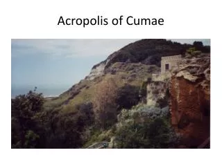
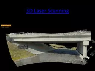
S-2361 3D Laser Scanning of Acropolis of ATHENS. 3 D scanning of the Wall and the Rock of Acropolis Athens and 3D model creation. Technical Specifications Scan density for the walls 1-2cm Scan density for the Rock 5cm Triangulation network with < 5mm accuracy Leveling <3mm accuracy)

E N D
3D scanning of the Wall and the Rock of Acropolis Athens and 3D model creation
Technical Specifications • Scan density for the walls 1-2cm • Scan density for the Rock 5cm • Triangulation network with < 5mm accuracy • Leveling <3mm accuracy) • Supervisor authority of the project was YSMA (authority of Hellenic calture)
Equipment • Trimble GPS 5800 • Trimble 5600 DR 200 total station • Trimble DiNi 0.3 digital level • Trimble GX laser scanner • External digital camera Canon EOS400D • Balloon with a Mamiya 22Mpixel camera
Field Work Field Work
Geodetic Background • Triangulation network consisted of 13 points (10 New triangulation points + 3 from National Coordinate Network) • Traverse points fully dependent on the triangulation network covering the whole area of interest • High accuracy leveling network
Scanning location selection Scanning location selected according to the following principles: • Maximum possible coverage with least possible scans (sample photo) • Scanning angles acceptable according to the specs • Multi dimensional overlap of successive scans • Logging and mapping of the scanned area coverage from each scan • Scanning always using the basic geodetic background points
Scanning location selection • Leveled stations • Unleveled stations • Targets
Principles of scanning procedure – Scanning orientation • Certain procedures were followed in order to achieve maximum absolute and relative orientation accuracy when scanning was performed with: 1) Trimble GX in horizontal position 2) Trimble GX inclined
Scanning • Scanner was leveled in known pre-surveyed position and oriented to a pre-surveyed point. • Additionally Trimble GX targets were used for orientation, which were previously measured with Trimble 5600 DR 200 Total Station. • Finally Trimble GX spheres were scanned which are ideal for relative orientation between scans. • Absolute orientation of successive scans was achieved using both first two methods while relative orientation was optimized by using common targets and spheres. • Significant overlapping also was usedin order to optimize relative orientation
External photos (land shots, balloon shots) Image resolution of internal Trimble GX camera was not enough according to the project specs. • For this reason external digital camera Canon EOS400D was used with 10Mpixel image analysis. • Also balloon vertical and horizontal photos were taken with a Mamiya 22Mpixel camera. Object shooting followed the following basic principles: • Shooting according to the basic rules to take photos • Shooting the object in right angles if possible • Shooting of complex surfaces from multiple angles • Balloon shooting of horizontal and encrypted by the rough terrain surfaces for appropriate texturing
Scan & Geodetic Statistics For the full coverage of the Wall internally and externally and the Rock: • 125 scans performed • more than 800 digital pictures were taken and used. • A total of 330.000.000 points were taken during scanning • The scan density was finally well above the specs • Better than 1cm accuracy For the geodetic network: • Triangulation network with < 3mm accuracy • Traverse points < 5mm accuracy • Leveling <2mm accuracy)
Supplementary and Vertical scans There were also gaps that were impossible to be covered with regular horizontal or inclined scans. • Gaps that were due to coverage errors were covered with supplementary scans. • Gaps that found and were due to the complex of the surface in most of the cases covered with two methods: 1) Vertical scans using a special installation to scan over the walls 2) DTM creation from photogrammetric models
Office Work Office Work
Triangulation Network – Leveling Network - Traverse Network • Trimble Geomatics s/w • Triangulation network, levelling network and traverses network resolution was done simultaneously using Least Square Adjustment technique
Scanning registration – Techniques applied • RealWorks s/w used for the processing of the scanning data. • Scans registering with: targets, spheres or by using overlapping scanned objects in successive scans. • RealWorks s/w ensures common resolution using different methods of registration to more than one scans simultaneously. • Memory limitations due to the huge model did not allow common resolution of the whole scanned object. • We used large common segments of it, with significant overlapping between them. • The mean orientation accuracy achieved was better than 1cm.
Location of scanning gaps With the common registration and unification of successive scans we manage to locate scanning gaps. Those gaps were covered as described above. • DTM provided by photogrammetric models were integrated to the rest of the point cloud automatically as the common geodetic background had as result that DTM was fully compatible with the rest of the model.
Scanning data filtering • Before surface creation point clouds from successive scans checked and filtered in the overlapping areas. Common point cloud created from multiple scans • By unifying scans a common point cloud created. • In order to be able to process the data due to the huge memory needed they were separated in sub-models
External digital photo orientation • In order to achieve the best possible accuracy in image matching the full density point cloud has to be used together with laser intensity info. • This way point cloud describes objects like a 3D photograph giving user the possibility to recognize and match common points with digital photos with great accuracy.
Equalise digital photos With Adobe Photoshop equalize digital photos. • This procedure eliminates the impact of different contrast and luminance due to different shooting environmental conditions • As a result texture differences coming from different photos are smoothed giving a homogeneous texturing to the object
Point cloud generalisation • In order to create surfaces it is a prerequisite for memory limitation reasons to generalize the point cloud. • The point cloud density for the walls decided to be finally 10cm, while the relevant one for the rock 20cm
3D model creation Point cloud segmentation • The object complexity had as result a very careful procedure of surface structuring, which was related not only with the surface complexity, but also with the external image shooting angles. • All the above has as a result a procedure of structuring sub surfaces and tailoring them with suitable overlapping in order to create a final product able to represent the real world. • All sub-surfaces have been created by point clouds that have been segmented accordingly. • The above procedure proved very complicated, demanding and time consuming.
Surface texturing • Surface texturing using the already matched external images was happening while we were creatring sub-surfaces. This way it was possible to control texturing to every single surface, and to select the most suitable image for this. Of course this is very complicated and time consuming. 3D model with texture • Following the above described procedure a 3D model of the walls and the rock of Acropolis Athens was createddescribingwithdetail and accuracy one of the most important and famousmonuments of the world.
Project Statistics • 3 months field work for Geodetic Infrastructure and Scanning (A team of two experienced surveyors) • 12 months (A team of one supervisor and two experienced RealWorks operators)