Software Architectures for Effective Component Assembly and Verification Techniques
1.05k likes | 1.18k Views
This paper explores software architectures focused on the proper assembly of components in systems. It highlights the significance of early problem identification and model checking to enhance the adequacy and validity of software products. The discussion includes the role of fixed software architecture, assumptions made during development, and strategies for synthesizing concurrent systems. It delves into challenges posed by deadlock and other verification issues in component-based systems, aiming to improve integration processes while maintaining efficient deadlock detection and verification methodologies.

Software Architectures for Effective Component Assembly and Verification Techniques
E N D
Presentation Transcript
Software Architectures for Correct Components Assembly Paola Inverardi Dipartimento di Informatica Universita’ dell’Aquila
Several people contributed to the general issue … • Alexander Wolf • Daniel Yankelevich • Sebastian Uchitel • Simone Scriboni • Massimo Tivoli
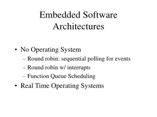
Presentation Scheme • Introduction • Motivation • Software Architectures and Component-based systems • Our Approach • Without a fixed Software Architecture Infrastructure • Assumptions • Partial Equivalence • The role of fixed Software Architecture • Synthesis • Conclusions + Future Work
Model construction should be part of the development process. Early identification of problems. Analysis by model checking. Increased confidence on the adequacy and validity of the final product. Mechanical verification of properties. In particular: Design of concurrent systems. Integration of components can introduce interaction problems that are hard to detect. Deadlock, starvation, safety and liveness properties. We believe that…
Motivation • In some cases existing model checking techniques can be too expensive to be applied successfully. • State explosion problem. • Techniques developed to accommodate a very broad range of concurrent systems.
The role of Software Architecture • Very high level system abstraction • Component and connectors • Architectural Properties Does this help in managing verification problems?
A bit of history: CP 2 3 1 4
CP: HTTP to improve the performance of UNIX-based WWW browsersby Garlan, Kindred, and Wing 1995. • compresses and uncompresses data across the network by using gzip compression/decompression program together with standard HTTP servers . • To assemble the Compressing Proxy from HTTP servers and gzip, use an adaptor to manage interfaces • The adaptor acts as a pseudo CERN HTTP filter, communicating with the upstream and downstream filters through a function-call interface, and with gzip using pipes connected to a separate gzip process.
CP components behavior • the upstream filter offers data along channel 1 (to AD and the downstream filter accept data along channel 4 (from AD). • GZ accepts data along channel 2 (from AD). It can then end its input and start offering data along channel 3 (to AD), and then end. • AD accepts data along channel 1 (from an upstream filter) and must wait until it has stopped accepting the data before it can offer data on channel 2 (to GZ).It can then end its output.
Verification: 2 deadlocks • the adaptor and gzip reach a state in which one is willing to output on channel 2 while the other is willing to output on channel 3. Both components are trying to output. • Both the adaptor and gzip are trying to input, one on channel 3 and the other on channel 2.
How do we verify CP SA? • We build the complete model of the 4 components (automata) • Model check to find deadlocks Fine but … Could have we been smarter?
Component-based systems • Component-based systems (CBS). • Growing acceptance in industry. • Characteristics of concurrent systems. • Can new (and more efficient) model checking techniques be developed in the context of CBS?
Component-based software development • Focuses on building large software systems by integrating previously-existing software components [SEI-CMU]. • Embodies the "buy, don't build" philosophy [Brooks 87]. • Boosted by… • Increase in the quality and variety of Commercial Off-The-Shelf (COTS) components. • Component integration technologies. E.g. COM & CORBA • Lower development and maintenance budgets. • Introduces a new approach to system design
Designing component-based systems Components are… • autonomous, decoupled, concurrent and possibly distributed entities. • with well defined interfaces for communication and synchronisation. Integration context provides… • abstraction framework for integrating components. E.g. network, operating system, data representation… • standard services: naming, yellow pages,… • capabilities for accessing component services. • Only simple interactions are supported. • For example: In CORBA only 3: Synchronous, Deferred Synchronous and One Way
Checking Deadlock Freedom in CBS Can we take advantage of… • Simple interaction mechanisms. • Flat architecture. … in CBS to check for deadlock freedom? YES How? Our approach is based on… • Extra information at component level: Assumptions. • Tightly coupled with: property and architecture. • Local checks. E.i. component to component. Results: • Efficient but incomplete deadlock detection.
Modelling • Component behaviour modelled using finite state machines. • Integration through parallel composition of component models. • In the context of CCS • Components: sequence and choice operators. E.g. Server = call.service.return.Server. • Integration: parallel composition and restriction operators. E.g. (C1 | C2 | ... | Cn) / L • Deadlock: (C1 | C2 | ... | Cn) / L can reach a state where no actions are possible.
Assumptions • Component requirement on its environment in order to guarantee a property in a specific integration context. • In a sense we are enhancing component semantics. • In our case we use: “My context never blocks me” or in other words “If I can perform action a, my context must be able to perform action a”. • Assumptions modeled in the same way as components.
Back to CP 2 3 1 4
Partial Equivalence • Relation between component assumptions and behaviours. • Compare assumptions with context. • Based on observational equivalence… A B: If A can do action a then B can also do a and continue to be observationally equivalent to A. • and allows partial matching…
When does not arise deadlock? • If no one of the components indefinitely blocks, the system does not deadlock • Each component always work when the environment always provides what it needs • All the components assumptions are satisfied by somebody else actual behavior
Partial Equivalence • Requires behaviours to be equivalent up to a set of stopping nodes. A B: If A can do action a then B can also do a and always continues to be observationally equivalent to A up to a certain set of stopping states.
Deadlock Freedom Checking Algorithm • Generate assumptions for each component. • Get assumption not completely matched. • Find a component behaviour that is partially equivalent to the assumption. • If not found return false. • Tag matched portion of assumption. • Change initial states in assumption and component behaviour. • If there are assumptions not completely matched go to 2. • Return true.
Stopping nodes Successful Matching
Complexity (For N graphs of K states): Space : O(K.N) vs. O(KN) Time : O(N3.K4.log(K)) vs O(KN) Incomplete: Some Deadlock Free Systems are not detected. Because of... Use of partial equivalence. Use of local approach to a global property. We have a prototype implementation. Hope to get feedback on where incompleteness appears… and how to make the approach more complete. Deadlock Freedom Checking Algorithm
What can we conclude? • Deadlock freedom checking algorithm that… • has very good space complexity and comparable time complexity. • is incomplete. • The concept of assumptions as an extension to component semantics. • Framework that might be extendable to other properties and integration contexts.
So far so good but … • We have modelled AC and AS component behaviors • We do not have hypothesis on the SA, i.e. on the interaction infrastructure • We are able to efficiently capture some behavioral problems Can we do better?
Let us re-consider the problem • software projects are based on the integration of COTS components. • Integration frameworks are fixed: CORBA, COM/DCOM, etc. • Component based technologies provide composition mechanisms
What is the problem? • The ability to establish properties on the assembly code by only assuming a relative knowledge of the single components properties. • A software architecture represents the reference skeleton used to compose components and let them interact: • interactions among components are represented by the notion of software connector.
What would we like to do: • extend the analysis of component-based systems to general safety and liveness properties; • provide recovery strategies besides property analysis; • (e.g.: avoid deadlock, starvation and guarantee safety and liveness) • make the whole approach as automatic as possible; • validate the approach on several concrete component-based architectural models.
Problem description • Given a set of components C and a set of properties P automatically derive an assembly A of these components which satisfies every property in P. • Basic ingredients: • the type of components we refer to (COTS, black-box); • the type of properties we want to check (functional, interaction behaviors); • the type of systems we want to build (component-based).
Basic idea • A simple software architecture structure which exploits the separation between functional behavior and Integration/Communication behavior. • Extra information at component level: component actual behavior and assumptions. • Our approach: • detect software anomalies; • remove software anomalies; • guarantee a given coordination policy.
Components information …Again • Component actual behavior • Component assumptions on its environment in order to guarantee a property in a specific integration context. • In the case of deadlock case we use: “My context never blocks me” or in other words “If I can perform action a, my context must be able to perform action a”. • How do we produce this additional information?
Modeling the system • Partial behavioural specification of the composed system: • bMSCs (basic Message Sequence Charts) • a bMSC describes a single scenario as a set of finite interactions between a set of components; • HMSCs (High-level Message Sequence Charts) • a HMSC provides the means for composing bMSCs as a directed graph where nodes represent bMSCs and edges indicate their possible continuations. • Specification of the behavioural properties to be enforced: • LTL (Linear-time Temporal Logic) • is a formalism for describing sequences of transitions between states in reactive system; • operators are provided for describing events along a single computation path.
Modeling … continuing • Component behaviour modelled using finite state machines: • finite-state CCS (Calculus of Communicating Systems); • LTS (Labelled Transitions System). • Integration through parallel composition of component models. • In the context of CCS • Components: prefix and choice operators. E.g. ServerA = (call_service1.return1 + call_service2.return2).ServerA • Integration: parallel composition and restriction operators. E.g. (C1 | C2 | ... | Cn) / L • Deadlock: (C1 | C2 | ... | Cn) / L can reach a state where no actions are possible.
A Connector Free Architecture (CFA) is a set of components directly connected in a synchronous way. In CCS : (C1 | C2 | ... | Cn) \ Ui=1..n Acti Connector Free Architecture Component 1 Component 2 channel channel Component 3
top Component 1 bottom channel 1 REQUEST top NOTIFICATION Connector bottom channel 3 channel 2 top top Component 2 Component 3 bottom bottom Connector Based Architecture • differences from C2 style: • synchronous message passing; • connectors cannot directly communicate; • connectors are only routing devices, without any filtering policies; • connectors have a strictly sequential input-output behavior. In CCS: (C1[f1] | C2 [f2] | ... | Cn[fn] | K) \U i=1..n Acti[fi] K is the synthesized connector, fi are suitable relabelling functions such that fi(a)=ai, for all aÎActi
local views of each component Component 1 Component 3 Component 1 Component 1 Component 3 Component 3 Connector code (assembly code) Connector Behavioral property deadlock-freeness Deadlock-free Connector Failure-free Connector Component 2 Component 2 Component 2 Connector Based Architecture Deadlock-free Connector Based Architecture Failures-free Connector Based Architecture Approach description: 3-step method Connector Free Architecture Component 1 Component 3 Component 2
Example • A client/server (single-layer) system: • 2 clients (C1, C2); • 1 server (C3). sLbl3=S3 sLbl2=S2 sLbl3=S3 sLbl1=S1 sLbl2=S2 sLbl1=S1 sLbl2=S2 sLbl3=S’3 sLbl3=S’’3 sLbl1=S1 sLbl2=S’2 sLbl1=S’1 sLbl3=S’’’3 sLbl1=S1 sLbl2=S’’2 sLbl2=S2 sLbl3=S3 sLbl1=S1 sLbl3=S3 sLbl1=S1 sLbl2=S2