Download
1 / 12
120 likes | 252 Views
MD Planning Fri – Sat (26. – 27.8.). Summary of MD transverse blow-up using transverse damper. Blow-up using band limited and white noise was prepared for beam 2.

E N D
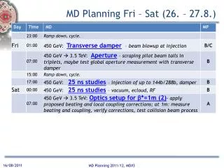
MD Planning Fri – Sat (26. – 27.8.) MD Planning 2011/12, MD#3
Summary of MD transverse blow-up using transverse damper • Blow-up using band limited and white noise was prepared for beam 2. • Initial tests on pilot bunches (max two pilots) spaced 2 us adjusted delays, gating etc. Demonstrated selectivity (one bunch left untouched, one blown-up) largest emittance observed was about 18-20 um, then too smallintensity for clean wirescanner measurement, but profile seemed to not increase beyond this; to be checked with collimator settings, but at first sight seems compatible with 5.7 sigma.
Summary of MD transverse blow-up using transverse damper • Used filling scheme with 2 batches of 6 bunches spaced at the nominal distance of 925 ns adjust excitation to middle of gap, then demonstrated that we can move controlled into first batch of 6 bunches; both planes checked plus loss maps done (moderate speed). It was demonstrated that it is possible to perform controlled loss maps with high intensity beam above safe limit. • Moved to single bunch; compared traditional loss map and damper loss map on single bunch, damper loss map with feedback on off. Achieved similar losses as with traditional loss maps, amplitude nicely controllable. Loss maps by the two methods show in the details some features that differ, to be analysed by collimation team.
MD IR Aperture (S. Redaelli et al) • measurements at 3.5 TeV (squeezed beams to 1.5m) • started after about 1h due to a problem with a collimator in IP7 for B1. This time was given to the previous MDers, who were working on the other beam. • Real measurements at top energy, with squeezed and separated beams, could start at about 9h30. • The measurements were aimed at measuring with the beam, the retraction between TCTs and triplets in IP1 and IP5, both in crossing and separation planes. We increased appropriate crossing bumps in both planes of each IP to explore the aperture in the expected limiting locations. We started from nominal separation (+/-0.7mm) and crossing (+/-120urad).
MD IR Aperture • The aperture was approached with bumps, keeping the TCT at settings that exposed the triplet by 0.5 sigmas at most. The first scan took about 2 hours. Then we got more confident on the procedure and could finish measurements in the separation and crossing planes of both IP1 and IP5. • We found a good aperture in both planes and IPs. So good that we want to take more time to see if we overlooked something. Had to open the TCT aperture to the following values before seeing primary losses at the triplet: IR1 - V -> 18.3 - 18.8 sigmasIR1 - H -> 19.8 - 20.3 sigmasIR5 - V -> >= 20.3 sigmas (corrector limit reached)IR5 - H -> 19.8 - 20.3 sigmas
MD IR Aperture • If preliminary estimates are confirmed possibility to squeeze further than 1 m at 3.5 TeV or to run at 1.0 m without going to tight settings or reducing the crossing. • As we had 30 min left, we squeeze to 1 m keeping the 120 urad crossing in IP1/5 and keeping the presently operational settings for collimators (relaxed). • At beta*=1m, the TCTs in IP1 and IP5 were set to 11.8 sigmas for the new optics, keeping the same centre as at 1.5 m (negligible difference of orbit with respect to 1.5 m). We made loss maps in the vertical planes for both beams to preliminary address the triplet protection with these settings. • Note that in parallel, we did measurements of the tune and coupling induced by the non linear errors in the triplet magnets. Tune and coupling shifts were indeed observed. More detailed analysis is required.
25 ns (part I) • Start 16h20. • 17h25 - Interruption from thunderstorms: • 7 sectors tripped • ventilation door at UL44 opened => access • some mini-quenches seen by the cryo ( on Q9+ Q10.R2, Q9L4, Q9.R4 Q10.L5 Q9+Q10.R5, Q9+Q10.L6, Q9.R6, Q9-Q10.L8) but no loss of cryostart • 19h03: Again ventilation door in UL44 opens by itself... interlock for this door seems to be in the SIS, so we mask until the door is fixed.
25 ns (part I) • 20h16: MD continuing, beam back • Injection of up to 48b, some apparent instability leads to loss of beam after 517 turns • 22h59: electrical perturbation on 3.3kV line caused a trip of the whole cryo plant at pt 2.... first estimate for recovery: 20+ hrs
MD Planning Fri – Sat (26. – 27.8.) To be revisited MD Planning 2011/12, MD#3
MD Planning Sun – Mon (28. – 29.8.) To be revisited Needs from experiments: -Luminometers on during beam-beam MDs and in the second slot of b*=1 m MD Planning 2011/12, MD#3