Download
1 / 2
20 likes | 130 Views
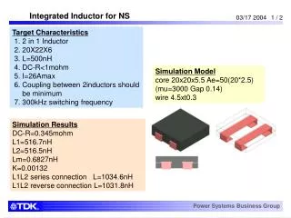
This document outlines the specifications and simulation results for an integrated inductor designed for NS targets. Key characteristics include a 500nH inductance, a maximum DC resistance of less than 1mΩ, and a maximum current rating of 26A. The inductors are tested under a switching frequency of 300kHz with a coupling requirement and specific core dimensions. The simulation indicates DC resistance values of 0.345mΩ and a coupling factor of 0.00132 between the inductors. Additionally, it presents flux density under various current conditions.

E N D
Integrated Inductor for NS Target Characteristics 1. 2 in 1 Inductor 2. 20X22X6 3. L=500nH 4. DC-R<1mohm 5. I=26Amax 6. Coupling between 2inductors should be minimum 7. 300kHz switching frequency Simulation Model core 20x20x5.5 Ae=50(20*2.5) (mu=3000 Gap 0.14) wire 4.5xt0.3 Simulation Results DC-R=0.345mohm L1=516.7nH L2=516.5nH Lm=0.6827nH K=0.00132 L1L2 series connection L=1034.6nH L1L2 reverse connection L=1031.8nH Power Systems Business Group
Flux Density at I=26A Same phase Current (26A) Reverse phase Current (26A) Bmax = 516.7nH x 26A / 50mm2= 269mT Power Systems Business Group