Download

1 / 18
180 likes | 352 Views
Walnut Bayou: A Dynamic River Simulation Model. Instructions for construction and basic use of the Walnut Bayou dynamic river simulation model. 4’x8’x ¾” plywood (grade depends on funding and expected quality of finished product: 1 2” deck screws: 1 small box

E N D
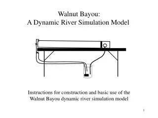
Walnut Bayou: A Dynamic River Simulation Model Instructions for construction and basic use of the Walnut Bayou dynamic river simulation model
4’x8’x ¾” plywood (grade depends on funding and expected quality of finished product: 1 2” deck screws: 1 small box 4’x8’x ¾” “Styrofoam” wall insulation (expanded polystyrene was actual label on prototype material): 1 1 ½” through-wall swimming pool fittings: 3 Water garden pump, ca. 130 gph: 1 Light gauge water garden liner: sized to box built, prototype required 10’x4’ ½” ID (inside diameter) clear plastic tube: 10’ 5/8” ID clear plastic tube: 4’ ½” PVC “90” female/female slip fittings: 9 ½” PVC “T” all female slip fittings: 2 ½” PVC pipe: 10’ ½” PVC female slip to ½” female thread adapter (check these dimensions with actual product in store, adapter must fit on ½” pipe and accept brass fitting for plastic tubes): 2 ½” brass thread to tube slip fit adapter (make sure brass fitting fits into ½” adapter, above): 2 ½” PVC ball valves: 3 Stainless steel band clamps to fit on ½” ID tubing: 3 1 ½” PVC “90” male/female slip fittings: 2 1 ½” PVC male thread to female slip fittings: 2 1 ½” PVC reducing bushing, male slip to ¾” female thread fitting (check these dimensions with actual product in store: 1 1 ½” PVC female thread to female slip coupling: 2 ¾” brass thread to tube slip fit adapter: 1 Stainless steel band clamp to fit on 5/8” ID tubing: 1 PVC pipe cleaner: 1 small can PVC pipe cement: 1 small can Ground walnut shells (trade name Lizard Litter at pet stores): 2 bags 5 gallon paint bucket Tools needed: Circular saw Jig saw (Skil saw) or large paddle drill bit (needed to cut large circular openings for swimming pool fittings in weir and side wall) ½” drill with philips (cross-point) screwdriver bit to drive wood screws Razor knife Carpenters square Carpenters tape measure Pencil Safety glasses Materials List(Based on 6’ x 2’ x 7” deep prototype)
Weir Basic box construction showing bottom, two sides, two ends, and weir. End Sides Bottom End • NOTES: • ¾” plywood sides and ends are glued and screwed to ¾” bottom and to each other on ends. Use 2” wood screws. (see details on subsequent pages) • Weir is glued and screwed between sidewalls, about 6” from end wall. Allow space for pool fitting at end of side wall. • Space 2” screws about 8” apart along bottom edge of sides and ends to hold the bottom. Start about 2” from ends. • 1 ½” through-wall swimming pool fittings are used to seal liner against plywood box structure. Pool equipment supplier can explain their use and installation. • Fittings in weir are left open to drain “watershed”. Place all holes as close to bottom as fitting will allow. • Fitting in side wall takes PVC pipe fittings to direct water into drain bucket. • Hole on side wall should be placed on whichever side is convenient for drainage of model. Placement is dependent on eventual location of model. Holes cut to fit 1 ½” swimming pool through-wall fittings
½” ID clear plastic water return line 5/8” ID clear plastic drain line Side view of overall system showing drain and feed lines, bucket sump and pump. ½” PVC valve assembly for headwaters of “watershed” (see plumbing diagrams for details) Use wedges or cabinet makers bench clamp to adjust slope of “watershed” Side Drain (see plumbing diagrams for details Weir Table or counter top ½” PVC ball valves ½ ” ID clear plastic water supply line Electric pump plugged into ground fault interrupt outlet 5 gallon bucket NOTE: ID = inside diameter for pipe and tube dimensions
Cutting diagram for 4’ x 8’ sheet of ¾” plywood Bottom – 30” X 72” End – 7” x 30” End – 7” x 30” Weir – 6 ¼” x 30” Side – 7” x 73 ½” Side – 7” x 73 ½” • Diagrams in plans are not to scale. • Dimensions can be adjusted to suit space and budget. • Minimum size is 2’ x 6’. • Minimum depth is 7”.
Weir design showing placement of holes and pool fittings • Use wood glue and 2” wood screws to secure sides, ends, bottom and weir to each other. • Use two screws at each joint. • Weir is inserted in one end of box with enough room for third pool fitting between end and weir. (See next diagram) • Prior to box assembly, pre-drill two suitably sized holes in weir, allowing for surrounding plastic ring on swimming pool fitting. • Pool fittings have a circular ring approximately ¾” wide surrounding the opening. • Place all three fitting as close to bottom as possible. Side Weir Pool Fittings End Wall Bottom
View showing location of side drain fitting • Pool fittings in weir are left open. • Pool fitting in side wall has PVC fittings to vary water level and adapt to drain tube. (See drain plumbing diagram) • Internal portion of pool fittings are placed in holes before installing liner. • After installing liner, cut through liner at fittings and install outer rings to hold liner in place. Pool supply dealer can provide details of fitting use. Side Weir End Wall Pool Fittings Side
Walnut shell substrate for “watershed” Two layers of Styrofoam inserted on top of plywood bottom • Side view of box showing placement of Styrofoam inserts to raise level of “watershed” and create “continental shelf” and “ocean” effect. • Inserts are two layers of ¾” Styrofoam extending from side to side and from upper end to within about 4” of weir. • ¾” Styrofoam can be purchased as 4’ x 8’ wall insulation at hardware store. • Secure Styrofoam to bottom of box using 1 ½” (bottom layer) and 2” (top layer) screws. Drain line end Valve assembly end “Ocean” or “Gulf” “Continental Shelf” End view of box looking toward weir and openings. Use angled Styrofoam inserts between weir and end of box to force drainage toward drain opening. 90 fitting is allowed to pivot in coupling in order to adjust water level Small block to support Styrofoam at a slight angle. Styrofoam layers Thickness of Styrofoam inserts in watershed and after weir should be adjusted for drainage. Prototype used two ¾” layers. Idea is to allow base of watershed area (top of Styrofoam) to be above “Ocean” level. Elevation of space after weir should be adjusted to just below openings in weir and drain hole. This allows good drainage of this area.
Liner Installation • After completion of box, with openings for weir and drain cut, insert inner portion of through-wall pool fittings into holes. (Swimming pool supplier can provide details on use.) • Liner is made of light-gauge pond liner sized to fit box. Prototype of 6’ x 2’ x 7”(deep) required liner of 4’ x 10’. Actual size of liner purchased depends on stock size available in stores. When buying liner don’t forget to allow for depth of box, including depth of weir. • Liner is draped over box and pushed into corners and along bottom edges as neatly as possible. Liner can be folded into corners of box roughly like the reverse of wrapping a package. Corner folds can be glued into place or stapled along top edge, so long as staples are well above expected water line. • Hold liner in place with staples or screws and grommets along top edge of box where liner wraps over top. • Install outer rings and gaskets for pool fittings to seal liner around holes and against box structure. • If wood working skills and equipment are sufficient, a cap can be cut and placed over liner to make the box look more attractive. Cap is made of solid wood approximately 2” wide and 1” thick. Cut “U-shaped” groove (dado) down center of cap. Groove should be approximately ¼” deep and 1” wide to allow cap to fit over top edge of box and liner. Screw cap in place. Cap also helps keep liner in place, taking pressure off of staples, to avoid possibly tearing the liner. • Overall construction of box could be a shop class project for school if facilities are available.
Detail of side wall drain fittings Liner wraps over top of box and is stapled or screwed in place with grommets on top edge of box. Liner goes behind through wall pool fittings, on inside of box. NOTE: ID = inside diameter for pipe and tube dimensions Staple Through-wall pool fitting Side 1 ½” male slip to female slip PVC 90. Glue into coupling. 1 ½” male slip to female slip PVC 90. Do not glue into coupling. Two 1 ½” PVC male thread to female slip couplings, threaded into pool fitting. Use Teflon tape on threads. Liner 1 ½” male slip to ¾” female threaded PVC reducing bushing, glued into 90 ¾” brass (“B”) male thread to slip fitting that accepts 5/8” ID plastic tube drain line. Use Teflon tape on threads. “B” Bottom 5/8” ID clear plastic tube for drain to bucket sump and pump
Plumbing and valve diagram for head of “watershed” Adjust distance between 90s to fit over top of box. End view “90” “90” “90” “90” Adjust distance between these two vertical pipes to “divide” box roughly into thirds. Side View Valve “90” End of box Walnut shell substrate for watershed “90” Side of box Side of box “90” “90” “T” Styrofoam inserts Outside end of box “T” Bottom of box ½” PVC pipe connects “Ts” and all other fittings. Liner • All fittings ½” PVC, with ½” PVC pipe connecting fittings • All fittings female slip fit, except adapters to brass tube fittings • PVC adapters (“A”) are female slip to female thread • Brass tube fittings are ¾” male thread to plastic tube fitting. Use Teflon tape on threads. • “Stars” in diagram represent valve handles on ball valves “90” “T” Valve Use of valve on return side of assembly allows for excess water to be routed directly back to sump. This reduces pressure on pump, preventing damage. Extra valve also helps regulate flow to the two “watershed” valves. “A” “A” “A” ½” ID clear plastic tubing Return side to sump bucket Inlet side from pump
Pump and Sump Operation • Pump is a small water garden or fountain pump rated at approximately 130 gallons per minute. • Always use a Ground Fault Interrupt (GFI) outlet to plug in the pump. This is an important safety feature to prevent electrocution should the pump or cord fail. GFI extension cords or outlet boxes can be purchased at hardware stores. • Be sure plastic tubing used to run from pump to “headwaters” valve assembly is sized to fit pump outlet. Tubing must also fit brass adaptors to connect to PVC assembly. Prototype used ½” ID (inside diameter) tubing. • Plastic tubing used for drain line should be larger than that used for pump line. Prototype used 5/8” ID tubing. Tubing must fit brass adapter from PVC drain opening. • Use stainless-steel band clamps to hold tubing in place on pump and brass adaptors. • Five-gallon bucket is used as sump for drain, with drain line from box dropping directly into bucket. • Pump is placed in bottom of bucket, with return line leading to “headwaters” valve assembly. • Use pivoting “90” fitting inside weir end of box to adjust water level of “ocean” on “watershed” side of box. • Water level should be adjusted to just below the top of the Styrofoam inserts of the “watershed.” This creates a “beach” effect or base level at that point. The top of the Styrofoam with walnut shell substrate is the base level or “continent”. The first step down is the “continental shelf”, and the second step or bottom of the box is the bottom of the “ocean.” • As the system runs, the substrate is washed onto the “continental shelf” first, then into the “ocean.” This forms a delta area and builds up land much like South Louisiana’s coastline. • Avoid getting too many walnut shells in the bucket sump. It will eventually clog the pump, causing it to shut off or burn out. Depending on the pump, it will automatically shut off to protect the motor. Cleaning the impeller should alleviate the problem should it shut down.
Walnut Shell Substrate for “Watershed” • Ground-up walnut shells are used as substrate for the system • Walnut shells can be purchased at pet stores under the trade-name “Lizard Litter.” There are probably other brands available, but this is what was used in the prototype. • Sand can be used, but it takes much longer for the river formations and changes to take place • Walnut shells are stable enough to hold the stream formations, yet light enough to erode away relatively quickly when trying to demonstrate how a river cuts its channel • Additional substrate experiments can be developed: • Mix sand, gravel and walnut shells to show what happens as a stream encounters different materials. Gravel becomes “boulders” in the stream. Caution, it’s hard to separate the material • Layer different substrates horizontally to show effects of down-cutting through layers of soil and rock: i.e. • Create bands of different substrates to show different effects: i.e. Walnuts Sand Gravel Gravel Sand Walnuts
Concepts to Consider • Meanders in rivers and streams – under most conditions the natural course of a stream is curved, not straight. The primary exception is a very steep river bottom, but even this curves somewhat. • Oxbow lake formation – as a river develops it will eventually cut off its meander bends, forming oxbow lakes. False River by New Roads is an oxbow lake. • Living in a floodplain does not pay in the long run – a river may seem docile enough while at normal stages, but eventually the rains will come and the river will rise out of its banks. That’s why they call it a “flood plain”!!! Better to live above the flood plain. • Building levees and channelizing streams helps, but it may just move the problem in time and/or space. Better to work with the natural system and not build in a floodplain. • The Mississippi River floods of 1993 proved that even the biggest levees can be breached given enough rain at the right place and time. Levees can create a false sense of security, promoting more construction in floodplains and resulting loss of wetland habitat. • Floodplains serve many useful purposes: water retention during heavy rains, wildlife habitat, water quality improvement, agriculture, …. • Floodplains can also serve many anthropogenic uses without risking loss of homes or other major structures: golf courses, parks, sport fields, light duty airports…. • Delta formation occurs at the continental shelf, or even in a lake - wherever a stream carries sediment into a standing body of water.
More Concepts to Consider • Stream conditions change with more rain, less rain, more slope, less slope, channelization, concrete lining, and other conditions. All these lead to changes in stream morphology or shape. Even a concrete lined ditch is not permanent because the water can eventually move the concrete, especially at the end of the concrete portion. • Use gravel or pebbles on top of walnut shell substrate to simulate rapids in the stream. • Insert rock, wood or floor tile across the width of the box and under the walnut shells to create ledges. Hard rock ledges in nature are the foundation of waterfalls, as the stream cuts through softer material. • Build “artificial” levees using 3-wire electrical conduit (flexes but holds its shape), clay or simply piles of walnut shells. This can simulate the problems encountered downstream of a leveed system, or the overtopping of levees in severe floods. • Use spray bottle or garden watering can to simulate rainfall and subsequent erosion effects. • Use Astroturf to simulate grass and how it protects the soil or banks from erosion. • Use Monopoly houses and hotels for towns and communities along the river or above the floodplain. • What else can you think of???????????????????????
Keywords • Hydrologic cycle: evaporation, precipitation, ground water, biological use, oceans, lakes, streams • Streamflow: base flow, surface runoff, watershed, drainage network, floodplain, drainage pattern change with change in streamflow, channel changes over time • Floods: causes, trends, land use, engineering for flood control and navigation • Wetlands, lakes, ponds: water table, natural impoundment, water balance, riverine wetland system, habitat and wildlife, infilling and eutrification • Water use: trends, supplies, dams and diversions, pollution, regulated uses
Tips for Using Walnut Bayou • Material for substrate: • Use the crushed walnut shells for fast demos of a small number of basic concepts, and for younger students or students at introductory level • Use sand, gravel, and small pebbles for more complex demos, long-term projects, and older or more advanced students • Construction: • Hinged construction is good for moving the model around. Construct without hinges if it is to be kept in one place. • A larger, more complex, model can be constructed if it is to stay in one place. • Cross-topic teaching: • Construction in shop • Earth science concepts (geography, geology, hydrology, ecology) • Math in science lab (measure materials, calculate stream discharge and sediment movement, extrapolate to a real-world situation … science fair project?) • English in science (write a lab report in good form) Please send comments, questions, suggestions to Al Hindrichs at: Al.Hindrichs@LA.GOV or by phone at (225) 219-3590.