RTCA DO-160F Lightning Testing
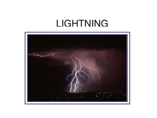
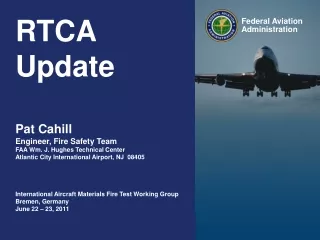
RTCA DO-160F Lightning Testing. Overview, updates, changes and what’s coming next! Michael Hopkins. DO-160 Brief History. F-106B (NASA 816) research aircraft during Storm Hazards Program in 1982. Note paint spots applied to aircraft that denote lightning attachment points. RTCA DO 160.

RTCA DO-160F Lightning Testing
E N D
Presentation Transcript
RTCA DO-160F Lightning Testing Overview, updates, changes and what’s coming next! Michael Hopkins
DO-160 Brief History • F-106B (NASA 816) research aircraft during Storm Hazards Program in 1982.Note paint spots applied to aircraft that denote lightning attachment points.
RTCA DO 160 • RTCA is the Radio Technical Commission for Aeronautics • Publishes DO 160 • Latest is DO 160F, issued in December 2007 and now available for downloading • Section 22 is “Lightning Induced Transient Susceptibility” • Serves the Aerospace, Automobile, Commercial Vehicle and Motorsport industries • AE-2 is responsible for Section 22 of RTCA DO 160 • Also responsible for Section 23 “Lightning Direct Effects • Fuel ignition and physical damage • And P-Static – buildup of charge on an airframe and its effects
Driving forces to requirements • Revisions E and F of DO 160 are driven by the use of composite materials used for airframe construction. • Boeing 787 Dreamliner • Airbus A380 • Embraer • Bombardier • And others…. • Many composites don’t conduct lightning currents the way metal airframes do; hence, the possibility of higher voltages and currents getting into cables and equipment on the aircraft.
Why the Revisions to Do-160 D? With Metal airframes, it is less likely that lightning energy will penetrate the airframe and cause problems with internal electronic systems. The airframe is a faraday cage and the lightning currents will flow over the surface of the aircraft with little or no resistance. Composite airframes present some resistance to the flow of lightning currents allowing voltages to develop. These voltages can then be coupled directly from the airframe material to internal wiring and into the avionics. Voltage!
Mil Std 461 vs. • It was the intention that parts or all of DO-160 Section 22 would be included in Mil Std 461F; however, due to disagreements between the Navy and Air Force regarding pin injection testing, it didn’t happen • SAE and RTCA were told in early 2007 that it would be 5 years before Rev G could be considered. • In May, the story changed and it was reported that not only have the Navy and Air Force come to some agreement regarding pin injection testing, a revision of 461 to include DO-160 testing would be possible by the end of 2008!
Mil Std 461 • In January 2008, it was sadly announced that due to the necessity of doing a 5 year review on Mil 464, the changes to Mil 461 would have to wait. • The latest word is that the review of Mil 464 will take 2 years and that the revision of 461 could begin by the end of 2009.
Section 22 Basics • There are 5 Test Levels and 6 Waveforms • Single stroke, multi-stroke, and multi-burst applications • 2 primary methods of testing • Pin Injection • Direct • Inductive coupling • Ground Injection • Cable Bundle • Inductive coupling • Ground Injection
Test Levels • Level 1 • Equipment and wiring are installed in a well protected environment • Level 2 • Equipment and wiring are in a partially protected environment • Level 3 • Equipment and wiring are in a moderately protected environment • Level 4 and 5 • Equipment and wiring are in severe electromagnetic environments
Waveforms • Waveform 1 - Current • Double exponential 6.4us X 69us (to 50%) • Waveform 2 – Voltage • Double exponential 100ns X 6.4us (at zero crossing) • Waveform 3 – Voltage/Current • Ringing wave, sine or cosine 1MHz and 10MHz • Waveform 4 – Voltage • Double Exponential 6.4us x 69us (to 50%) • Same shape as Waveform 1 except this ones voltage • Waveform 5A – Voltage/Current • Double Exponential 40us X 120us (to 50%) • Waveform 5B – Voltage/Current • Double Exponential 50us X 500us (to 50%)
Waveform Application • Multiple Stroke (Multi-Stroke) • Multiple Burst (Multi-Burst)
Safety issues • The waveforms used for lightning testing in DO-160 Section 22 contain considerable energy – enough to be lethal under the right conditions. • It is imperative that labs doing this kind of testing take all the necessary measures to insure safety procedures are observed. • Grounding – Electrical codes • Floating Scopes ?? --- NEVER!! • Exposed components and circuits – ever see a capacitor explode ? • Restricted access to the test area – is it ? • One hand in your pocket ?
Available Testers • Prior to this year, there was only one commercially available test system for Section 22 of DO-160. • As a result, there is a lot of home-brew equipment in use today similar to the telecom industry in the early ’80s. Much of the equipment in use today may have some of the same problems the telecom industry had before moving towards commercially available testers.
Available Testers • Before the telecom industry moved toward commercial testers for lightning, they were experiencing a range of problems, including: • Exposed components • Difficult to maintain • Time consuming to use due to set-up requirements • Requires engineers to run the tests • Availability of high energy components in small quantities limited • Ceramic power resistors, large storage caps, large inductors, magnetics • Lack of correlation between testers • Sometimes standards written loosely to accommodate construction problems • SAFETY --- Biggest issue…
Changes from DO-160E to DO-160F There were a number of changes made to Section 22 of Rev F, both technical and editorial. I’ll highlight some of the main points in the following slides.
22.1 Purpose • Two clarifications added to the Purpose (22.1) • Rev E: stated the procedures “apply idealized waveforms to verify the capability of equipment to withstand the effects of lightning induced electrical transients.” • Rev F: modified to say the procedures are, “… provided to verify the capability of equipment to withstand a selection of transients defined in this section which are intended to represent the effects of lightning.” • The Note at the end of 22.1 was in italics for emphasis, but the italics have been removed, and references to different tests being performed was removed. • The intent of the change is to make it clear Section 22 testing doesn’t necessarily guarantee it will survive in the aircraft --
22.2 Definitions • Local Ground • Limited what can be considered “local” ground to equipment connected via a ground strap of less than 1 meter. • Rev E only specified that the equipment be bonded or connected to the same part of the airframe structure. • Added a definition for “Transfer Impedance” as the ratio of core wire open-circuit voltage to the shield current. Z = Voc/I According to 22.5.2 section c., for cable bundle testing, if the bundle contains shielded cables and those shields cannot be disconnected for testing (they are needed for correct operation), then you must determine the “transfer impedance” so that one can decide what levels to test at and what waveforms to use – V or I. Transfer impedance was never defined in Rev E.
22.3 Categories • B3G43 (An example) • B = Pin test Waveform Set using Waveform B (must be A or B) • 3 = Pin test Level 3 – could be 1 through 5 • G = Cable Bundle Test using Waveform Set G (must be C thru K) • 4 = Level 4 for Cable Bundle tests, which requires both single stroke and multiple stroke tests – could be 1 through 5 and need not be the same as for pin injection tests • 3 = Level 3 for Cable Bundle tests using multi-burst (could be other levels) • A sentence was added to make it clear that the Pin test waveforms and level need not be the same, as indicate in the above example.
22.3 Categories • Table 22-1 listing Test Requirements has been split • In Rev E, there is one table • Covers both Pin Injection and Cable Bundle Testing • In Rev F, the table is split into • Table 22-1.1 for Pin Injection Test Requirements • Table 22-1.2 for Cable Bundle Test Requirements • This is more consistent with Table 22-2, Test Levels, is already split in a similar way.
Table 22-1.1 and 22-1.2 Aperture coupling is coupling induced through openings in a metal airframe. Resistance coupling is due to voltages developed on the surfaces of composite material airframes. A, C, E, G and J for aperture coupling B, D, F, H, and K for resistance coupling C through F for cable bundle single stroke G through K for cable bundle single, multi-stroke and multi-burst Z means other tests were conducted
Table 22-1.2 Changes • Waveform 4 removed from Category C and G. • Waveform 4 replaces Waveform 5A in D and H. • Waveform 1 not included in F and K because it would be redundant • Waveform 3 is required which has a faster risetime • Waveform 5A is required which has higher energy. • Waveform 5A was listed for a voltage situation under Category D and H in Rev E, but was never defined.
22.4 General Test Requirements • a. (4) External Ground Terminal • When an external ground terminal exist for connection on the EUT, it generally should be connected to the ground plane. The question was, how (or if) this ground wire is treated in the cable bundle – • Rev E: It should NOT be included as a parallel current path unless it’s routed with the cable bundle for its entire length. • Rev F: Adds, “… unless this is otherwise specified in the equipment installation instructions.” • Rev E: “If present at the unit under test during ground injections tests, these grounds should be tied to the EUT chassis.” • Rev F: Adds, “… or the injection has to be applied at the remote end.” • Bottom Line: No external ground connection should constitute a parallel path for the injected lightning current, and in the case of an external ground normally running with the cable bundle, it should be tested that way.
External Ground Terminal If the External ground terminal is connected to ground, there won’t be any current injected on the cables. If the External ground must be connected for the test, then an alternate injection point is to be used.
22.5.1 Pin Injection Tests • Paragraphs now labeled a. to i. • Added item d. “For pin injection testing, waveform 3 shall be applied at 1.0 MHz (+/-20%).” • Clarified the paragraph regarding the remote load impedance characteristics • This is the impedance, “…between the remote pin and airframe ground at that extremity (including the fact that the dielectric strength characteristics of the remote load can tolerate the open circuit voltage of the transient generator) are specified in the equipment installation requirements…” • What’s this mean: If in a normal installation an EUT is connected to remote loads or sources, the impedance of those remote loads and sources can be simulated by adding an appropriate resistance between the tester and EUT – with limits: 75 ohms for Waveform 3.
Figure 22-13 Pin Injection for Signal Pins • Added optional remote load impedance as described in 22.5.1 for certain tests.
22.5.1 Procedures – Generator Calibration • d. Reference to Table 22-2 Note 4 removed. • In many places in Rev F, notes that are requirements have been moved into the body of the text and not just left as “notes”. • e. Modified to make it clear that when verifying the source impedance of the generator by using a non-inductive resistor equal to the generator source impedance that wave shape parameters and amplitude reduces to ½ of the open-circuit set voltage – not just the amplitude as in Rev E. • The Note at the end of the procedure is now included in paragraph e. This note allows the use of taking the ratio between open-circuit voltage and short-circuit current as the effective source impedance of the generator: Zg = Voc/Isc. • Same reasoning as for “d.” above.
22.5.1.2 Procedures – Test Sequence Added a timing requirement: “The maximum time between application of each transient shall be no greater than 1 minute” Much discussion regarding power ratings of protective devices, effects of faster testing on failure rates, etc…
22.5.2 Cable Bundle Tests Section 22.5.2 has been significantly expanded to provide as much guidance as possible to the user to insure that tests are done correctly – especially when a test provides unexpected results. The following few slides with go through a few of the points.
22.5.2 Cable Bundle Tests – a brief overview • For an individual conductor, core wire current need not exceed the corresponding pin test short-circuit current – straight forward reasoning. • For multi-stroke and multi-burst, random is achieved through timing – “random” is always a point of discussion. • If IT cannot be reached – cable too long, level > 5, or requested by system installer, some shields can be disconnected and core wires pulsed directly. • Cable bundle single and multi-stroke tests can be combined, but first of the multi-stroke must be at the level required for a single stroke test • For cable bundles, waveform 3 is applied at both 1MHz and 10MHz • Waveform 1 can be applied using either cable or ground injection methods • A test is always acceptable if the test level is reached before the limit level.
22.5.2 Cable Bundle Tests – a brief overview (cont) • Voltage waveforms – if correct during a test, generator performance verification isn’t required. When monitoring the current: • Waveform 2: If IL is reached and a Waveform 1 is produced, test is acceptable. If not, a Waveform 1 current test is required. • Waveform 3: Test is acceptable if V and I wave shapes are the same and either VT or IL is reached. • Waveform 4: If IL is reached before VT and I rise/duration are equal to or longer than V rise/duration, test is okay. Shorter duration I during verification is NOT acceptable. If generator cannot produce a compliant current, Waveform 5A must be used. • Waveform 5A: can be defined as a voltage wave for testing cables with shield wires lifted. The test level for Waveform 4 is used.
22.5.2 Cable Bundle Tests – a brief overview (cont) • Current waveforms – Waveforms 1, 5A and 5B • For Waveform 1, if correct during a test, generator performance verification isn’t required. • When monitoring the voltage if VL is reached before IT and V waveform risetime is shorter and duration longer than Waveform 2 during verification, test is acceptable. • When measuring voltage, spikes and HF noise are to be ignored When measuring voltage, spikes and HF noise are to be ignored
22.5.2.1 Cable Induction Tests Rev E stated that local ground leads, “… (less than 1 meter in length) grounded directly to the test bench…” are not required to be tested. Rev F re-affirms that testing of local grounds is NOT required, and that local grounds are not to be included in the bundle under test.
Tables 22-2 and 22-3 • For Table 22-2 • In Rev E, only the Voltage waveform was listed. • In Rev F, both Voltage and Current waveforms are shown in the table for clarity. • For Table 22-3 • In Rev E, only the Current waveform was listed. • In Rev F, both Voltage and Current waveforms are shown in the table for clarity
Figure 22-17 and 19 Power supply protection capacitor value changed to 28,000uF accommodate longer duration waveforms at higher levels. An even larger capacitor may be required to avoid damage to power supplies. Figures are modified to show configurations for all power port input situations.
What’s next ? Users guide; Mil 461 (eventually) • Work is currently underway to produce a users guide for Section 22 of DO-160 • Each section of DO-160 will have a corresponding section in the users guide. • The intention is to clarify points where there is still confusion and ambiguity. • “Random” • Use of resistors to simulate remote impedances • Transfer Impedance – how to calculate ?? • Can we get this into Mil 461 sooner rather than later ?
Thermo Fisher Scientific – Lowell Business Unit • We manufacture simulators for testing systems, sub-systems, and components for the effects of: • Electrostatic Discharge - ESD • Electrical Fast Transients – EFT • Surge – Lightning • Dips & Interrupts • We also manufacture test systems for testing individual semiconductor devices for their susceptibility to ESD and Latch-Up phenomena. Thermo Fisher Scientific Michael Hopkins Lowell Research Center +1 603 765 3736 Lowell, MA 01852 michael.hopkins@thermofisher.com +1 978 275 0800