Download
1 / 4
40 likes | 190 Views
This guide explores the analysis of an LRC circuit using phasor diagrams in an XY coordinate system. Arrows in the phasor diagram serve as vectors, representing the peak voltage across each circuit element. We will determine the total impedance (Z) of the circuit, delve into resonance phenomena, and explain how LC oscillations occur. Additionally, we will discuss the importance of impedance matching for efficient power transfer between circuits. This comprehensive resource includes essential formulas and illustrative diagrams for better understanding.

E N D
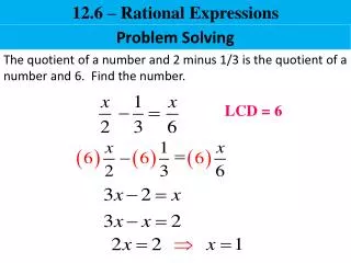
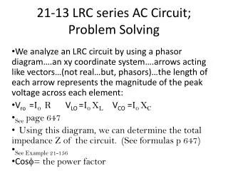
21-13 LRC series AC Circuit; Problem Solving We analyze an LRC circuit by using a phasor diagram….an xy coordinate system….arrows acting like vectors…(not real…but, phasors)…the length of each arrow represents the magnitude of the peak voltage across each element: Vro =I0 R VLO =I0 XLVCO =I0 XC See page 647 Using this diagram, we can determine the total impedance Z of the circuit. (See formulas p 647) See Example 21-156 Cosf= the power factor
21-14 Resonance in AC Circuits; Oscillators • See formulas page 649. • See diagrams page 649 • Resonant frequency f0 = (1/2p)( ) • When R is very small, we can refer to LRC as an LC circuit. • The energy in an LC circuit oscillates, at frequency, between the inductor and the capacitor , with some being dissipated in R. • See page 649
This process of the charge flowing back and forth from one plate of the capacitor to the other, through the inductor, continues to repeat itself. This is called an LC oscillation or an electromagnetic oscillation. • LC circuits are used in oscillators.
21-15 Impedance Matching • Often, two circuits are attached and they must be matched to the same impedance. • Maximum power is transmitted between two circuits, when the output impedance of one matches the input impedance of the second circuit. • See page 651