Download
1 / 9
90 likes | 111 Views
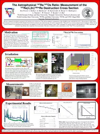
This study aims to understand CO2 boiling for improved design of IBL cooling systems. Observations reveal superheated liquid behavior before and after boiling, necessitating tracking. The complex phenomenon requires a dedicated setup to capture temperature variations and pressure dynamics. Superheating tracing is crucial for assessing mass flow rates, saturation temperatures, and heat flux. The setup outline includes specific requirements for superheating measurements and flow pattern visualization for better insights and comparison with numerical models.

E N D
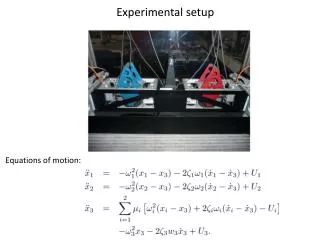
New experimental setup for CO2 boiling onset phenomenon analysis Nicola Suzzi
Objective • Understanding of CO2 boiling required for a better design of IBL cooling system: • Superheated liquid observed before and after boiling onset: why? Is it possible to trace it? • (superheated liquid: ) • Discontinuities in temperature behavior observed: boiling triggered multiple time, flow pattern discontinuities? • Boiling is a complex phenomenon: many flow pattern transitions involved = physical discontinuities. • A dedicated setupis required: • Temperature to be measured along the experiment allowing for flow pattern transitions capturing; • Coupling of temperature measure and pressure knowledge (thus ) required. • Superheating tracing as a function of mass flow rate, saturation temperature, heat flux. • Looking insidethe pipe fortracing the flow pattern transitions and comparing with numerical model prediction; • Roughness of the pipe(thus pipe material) not investigated yet: interface problems strongly influenced by contact angle.
Setup outline flange 800÷1000 mm high vacuum : bar power supply D=2÷3mm vacuum feedthrough P , T - + 300 mm - P , T cables storage 25x50 mm T sensors support transparent plate P , T P , T - + D = 2.8mm pipe cut and pressed to transparent plate power supply high pressure feedthrough
Setup requirements • a) Superheating measurements: • More materials need to be tested (titanium and alloy); • One diameter dimension (2÷3mm); • 1.5 m of pipe, 1.0 m heated by Joule effect, covered by 31 temperature sensors (5 cm → 1 sensor); • Insulation obtained by high vacuum; • Only one material at a time can be tested using the proposed setup, thus flexibility is required; • Need of accurate evaluation of saturation temperature; • b) Flow pattern visualization: • Transparent glass plate used for flow visualization, half pipe cut and fixed between the transparent plate and the metal support plate (see figure in next slide); • The same configuration of IBL should be considered: titanium pipe, diameter (hydraulic diameter ). • Heating by Joule effect; • Temperature and pressure sensors at inlet and outlet; • High pressure feedthrough required for electrical connection; • Electrical wires and pipe must not touch the metal plate; • Still pending: high pressure feedthrough of electrical wires? home-made setup or existing sight glass for high pressure? • Flexibility reached by connecting the experimental tube just after the flange; • Pressure sensors mounted after diameter change; • Still pending: type of temperature sensors to be used? vacuum feedthrough? vacuum chamber too small, need of home made vacuum chamber? vacuum system in SR1 not available.
Drawing of the flow pattern visualization setup 2.8 mm pipe cut and mounted here transparent glass plate O-ring/sealing CO2 plastic rail (also useful for avoiding electrical connection with metal plate) SECTION OF THE METAL PLATE AND THE GLASS COVER temperature sensor here CO2 connector for electrical feedthrough (pipe heated by Joule effect!!) support plate
Temperature sensors and electrical feedthroughs • K type thermocouples: • smaller and easy to mount/move from the setup (it can be eventually possible to mount 2 sensors per pipe section); • require special connector for vacuum feedthrough; • class 1 tolerance: ±1.5°C in -40÷375°C. • T type thermocouples: • class 1 tolerance ±0.5°C in -40÷125°. • PT100 platinum resistance thermometers: • bigger, thus more difficult to store inside the setup and to mount; properly, 4 wires to be connected instead of two; • class A tolerance: ±0.15°C at 0°C. Vacuum feedthrough: Accu-Glass Products 50 pin HV connector 51x89mm on bulkhead flange + Accu-Glass Products 15 pin HV connectoron bulkhead flange (at least) High pressure feedthrough: Kemlon PMS glass sealed feedthrus 16-B-01498. An "O" ring is employed to seal the connector to the bulkhead.
Flow pattern visualization setup: sight glass • High pressure sight glasses: • > METALGLAS Rectangular SightglassFittigns, Type LSG-HP • > JERGUSON Flat Glass Gage, Series T-300L • Pressure drop at the setup inlet may induce boiling before flow visualization. How to predict pressure drop, so that I know the required sub-cooling before the flow visualization setup? base frame not needed!! Sealing gaskets
Flow pattern visualization setup: components sizing (in case sight glass do not fit) • Metal support: number of screws • Glass thickness: Timoshenko formulas L=78mm O-ring /sealing B=1191mm
Conclusion and future work • Superheating measurements: • High vacuum station ( bar ) needed for proper insulation; • Large vacuum chamber is needed; • Next step: • > Temperature sensors can be ordered; • > Flange for electrical high vacuum feedthrough • can be ordered: Accu-Glass 50 pin HV connector – • 570.00€; • b) Flow pattern visualization: • Flow pattern visualization of an IBL look-like configuration is possible. • Flow visualization setup also allows for a posterioritracing of the superheating; • Next step: • > High pressure sight glass and support: JERGUSON • T-300L or new design? • > Electrical connector for high pressure • feedthrough can be ordered: Kemlon PMS glass • sealed feedthrus16-B-01498(price to be • checked); • > Metal plate and plastic rail must be designed;