How Fuel Cells Work
580 likes | 752 Views
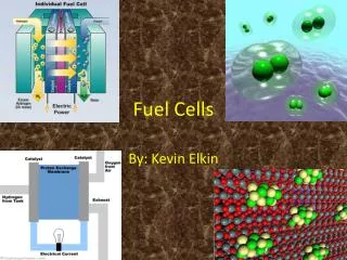
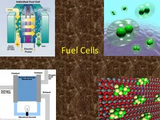
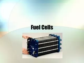
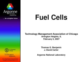
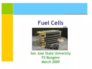
How Fuel Cells Work. Fuel Cells ( 燃料電池 ): Making power more efficiently and with less pollution. Fuel Cell - an electrochemical energy conversion device. To convert the chemicals hydrogen and oxygen into water, and in the process it produces electricity.

How Fuel Cells Work
E N D
Presentation Transcript
How Fuel Cells Work Fuel Cells (燃料電池): Making power more efficiently and with less pollution.
Fuel Cell- an electrochemical energy conversion device • To convert the chemicals hydrogen and oxygen into water, and in the process it produces electricity. • Battery (電池): the other electrochemical device that we are all familiar. • A battery has all of its chemicals stored inside, and it converts those chemicals into electricity too. • This means that a battery eventually "goes dead" and you either throw it away or recharge it.
For a fuel cell • Chemicals constantly flow into the cell so it never goes dead. • As long as there is a flow of chemicals into the cell, • the electricity flows out of the cell. • Most fuel cells in use today use hydrogen and oxygen as the chemicals.
Fuel Cell Descriptions • Fuel Cells generate electricity through an electrochemical process • In which the energy stored in a fuel is converted directly into DC electricity. • Because electrical energy is generated without combusting fuel, • Fuel cells are extremely attractive from an environmental stand point.
Attractive characteristics of Fuel Cell • High energy conversion efficiency • Modular design • Very low chemical and acoustical pollution • Fuel flexibility • Cogeneration capability • Rapid load response
It consists of three components - a cathode, an anode, and an electrolyte sandwiched between the two. • Oxygen from the air flows through the cathode • A fuel gas containing hydrogen, such as methane, flows past the anode. • Negatively charged oxygen ions migrate through the electrolyte membrane react with the hydrogen to form water, • The reacts with the methane fuel to form hydrogen (H2) & carbon dioxide (CO2).
This electrochemical reaction generates electrons, which flow from the anode to an external load and back to the cathode, • a final step that both completes the circuit and supplies electric power. • To increase voltage output, several fuel cells are stacked together to form the heart of a clean power generator.
Cool Fuel Cells • Fuel cells promise to be the environmentally-friendly power source of the future, • but some types run too hot to be practical. NASA-funded research may have a solution.
All fuel cells have the same basic operating principle. • An input fuel is catalytically reacted (electrons removed from the fuel elements) in the fuel cell to create an electric current. • Fuel cells consist of an electrolyte material which is sandwiched in between two thin electrodes (porous anode and cathode). • The input fuel passes over the anode (and oxygen over the cathode) where it catalytically splits into ions and electrons. • The electrons go through an external circuit to serve an electric load while the ions move through the electrolyte toward the oppositely charged electrode. • At the electrode, ions combine to create by-products, primarily water and CO2. Depending on the input fuel and electrolyte, different chemical reactions will occur.
With thousands of diaphragm compressor installations worldwide, you can trust PPI to handle the difficult applications. PPI has the hydrogen compressor engineering and manufacturing experience you can count on.
SOLID OXIDE FUEL CELL STACK PROVIDER • HTceramix's SOFConnexTM based stack
Four primary types of fuel cells They are based on the electrolyte employed: • Phosphoric Acid Fuel Cell • Molten Carbonate Fuel Cell • Solid Oxide Fuel Cell • Proton Exchange Membrane Fuel Cell
Phosphoric Acid Fuel Cells -PAFCs • The most mature fuel cell technology in terms of system development and commercialization activities. • Has been under development for more than 20 years • Has received a total worldwide investment in the development and demonstration of the technology in excess of $500 million. • The PAFC was selected for substantial development a number of years ago because of the belief that, among the low temperature fuel cells, • It was the only technology which showed relative tolerance for reformed hydrocarbon fuels and thus could have widespread applicability in the near term.
PAFC Design and Operation • The PAFC uses liquid phosphoric acid as the electrolyte. • The phosphoric acid is contained in a Teflon bonded silicone carbide matrix. • The small pore structure of this matrix preferentially keeps the acid in place through capillary action. • Some acid may be entrained in the fuel or oxidant streams and addition of acid may be required after many hours of operation. • Platinum catalyzed, porous carbon electrodes are used on both the fuel (anode) and oxidant (cathode) sides of the electrolyte.
Fuel and oxidant gases are supplied to the backs of the porous electrodes by parallel grooves formed into carbon or carbon-composite plates. • These plates are electrically conductive and conduct electrons from an anode to the cathode of the adjacent cell. • In most designs, the plates are "bi-polar" in that they have grooves on both sides - one side supplies fuel to the anode of one cell, while the other side supplies air or oxygen to the cathode of the adjacent cell. • The byproduct water is removed as steam on the cathode (air or oxygen) side of each cell by flowing excess oxidant past the backs of the electrodes. • This water removal procedure requires that the system be operated at temperatures around 375oF (190oC). • At lower temperatures, the product water will dissolve in the electrolyte and not be removed as steam. At approximately 410oF (210oC), the phosphoric acid begins to decompose.
The byproduct water is removed as steam on the cathode (air or oxygen) side of each cell by flowing excess oxidant past the backs of the electrodes. • This water removal procedure requires that the system be operated at temperatures around 375oF (190oC). • At lower temperatures, the product water will dissolve in the electrolyte and not be removed as steam. At approximately 410oF (210oC), the phosphoric acid begins to decompose. • Excess heat is removed from the fuel cell stack by providing carbon plates containing cooling channels every few cells. • Either air or a liquid coolant, such as water, can be passed through these channels to remove excess heat.
Electrochemical reactions in PAFC • At the anode: • Hydrogen is split into two hydrogen ions (H+), which pass through the electrolyte to the cathode, and • two electrons which pass through the external circuit (electric load) to the cathode. • At the cathode: • the hydrogen, electrons and oxygen combine to form water.
PAFC Performance Characteristics • PAFC power plant designs show electrical efficiencies in the range from 36% (HHV) to 42% (HHV). • The higher efficiency designs operate with pressurized reactants. • The higher efficiency pressurized design requires more components and likely higher cost. • PAFC power plants supply usable thermal energy at an efficiency of 37% (HHV) to 41% (HHV). • A portion of the thermal energy can be supplied at temperatures of ~ 250oF to ~ 300oF. • However, the majority of the thermal energy is supplied at ~150oF. • The PAFC has a power density of 160-175 watts/ft2 of active cell area
Molten Carbonate Fuel Cells - MCFC • A molten carbonate salt mixture is used as its electrolyte. • They evolved from work in the 1960's aimed at producing a fuel cell which would operated directly on coal. • While direct operation on coal seems less likely today, • The operation on coal-derived fuel gases or natural gas is viable.
Molten Carbonate Salt used as Electrolyte in MCFC • A molten carbonate salt mixture is used as its electrolyte. • The composition of the electrolyte (molten carbonate salt mixture) varies, but usually consists of lithium carbonate and potassium carbonate. • At the operating temperature of about 650oC (1200oF), the salt mixture is liquid and a good ionic conductor. • The electrolyte is suspended in a porous, insulating and chemically inert ceramic (LiAlO3) matrix.
Reactions in MCFC • The anode process involves a reaction between hydrogen and carbonate ions (CO3=) from the electrolyte. • The reaction produces water and carbon dioxide (CO2) while releasing electrons to the anode. • The cathode process combines oxygen and CO2 from the oxidant stream with electrons from the cathode to produce carbonate ions which enter the electrolyte. • The need for CO2 in the oxidant stream requires a system for collecting CO2 from the anode exhaust and mixing it with the cathode feed stream.
Description of reactions in MCFCs • The anode process involves a reaction between hydrogen and carbonate ions (CO3=) from the electrolyte. • The reaction produces water and carbon dioxide (CO2) while releasing electrons to the anode. • The cathode process combines oxygen and CO2 from the oxidant stream with electrons from the cathode to produce carbonate ions which enter the electrolyte. • The need for CO2 in the oxidant stream requires a system for collecting CO2 from the anode exhaust and mixing it with the cathode feed stream.
As the operating temperature increases, • the theoretical operating voltage for a fuel cell decreases and with it the maximum theoretical fuel efficiency. • On the other hand, increasing the operating temperature increases the rate of the electrochemical reaction and • Thus increases the current which can be obtained at a given voltage. • The net effect for the MCFC is that the real operating voltage is higher than the operating voltage for the PAFC at the same current density. • The higher operating voltage of the MCFC means that more power is available at a higher fuel efficiency from a MCFC than from a PAFC of the same electrode area. • As size and cost scale roughly with electrode area, this suggests that a MCFC should be smaller and less expensive than a "comparable" PAFC.
As size and cost scale roughly with electrode area, this suggests that a MCFC should be smaller and less expensive than a "comparable" PAFC. • The MCFC also produces excess heat at a temperature which is high enough to yield high pressure steam which may be fed to a turbine to generate additional electricity. • In combined cycle operation, electrical efficiencies in excess of 60% (HHV) have been suggested for mature MCFC systems. • The MCFC operates at between 1110°F (600°C) and 1200°F (650°C) which is necessary to achieve sufficient conductivity of the electrolyte. • To maintain this operating temperature, a higher volume of air is passed through the cathode for cooling purposes.
As mentioned above, the high operating temperature of the MCFC offers the possibility that it could operate directly on gaseous hydrocarbon fuels such as natural gas. • The natural gas would be reformed to produce hydrogen within the fuel cell itself. • The need for CO2 in the oxidant stream requires that CO2 from the spent anode gas be collected and mixed with the incoming air stream. • Before this can be done, any residual hydrogen in the spent fuel stream must be burned. • Future systems may incorporate membrane separators to remove the hydrogen for recirculation back to the fuel stream.
At cell operating temperatures of 650oC (1200oF) noble metal catalysts are not required. • The anode is a highly porous sintered nickel powder, alloyed with chromium to prevent agglomeration and creep at operating temperatures. • The cathode is a porous nickel oxide material doped with lithium. • Significant technology has been developed to provide electrode structures which position the electrolyte with respect to the electrodes and maintain that position while allowing for some electrolyte boil-off during operation. • The electrolyte boil-off has an insignificant impact on cell stack life.
A more significant factor of life expectancy has to do with corrosion of the cathode. • The MCFC operating temperature is about 650oC (1200oF). • At this temperature the salt mixture is liquid and is a good conductor. • The cell performance is sensitive to operating temperature. • A change in cell temperature from 650oC (1200oF) to 600oC (1110oF) results in a drop in cell voltage of almost 15%. • The reduction in cell voltage is due to increased ionic and electrical resistance and a reduction in electrode kinetics.
Solid Oxide Fuel Cells • The Solid Oxide Fuel Cell (SOFC) uses a ceramic, solid-phase electrolyte which reduces corrosion considerations and eliminates the electrolyte management problems associated with the liquid electrolyte fuel cells. • To achieve adequate ionic conductivity in such a ceramic, however, the system must operate at about 1000oC (1830oF). • At that temperature, internal reforming of carbonaceous fuels should be possible, and the waste heat from such a device would be easily utilized by conventional thermal electricity generating plants to yield excellent fuel efficiency.
The fuel cell will compete with many other types of energy conversion devices, including • the gas turbine in city's power plant, • the gasoline engine in your car and • the battery in your laptop. • Combustion engines like the turbine and the gasoline engine burn fuels and • use the pressure created by the expansion of the gases to do mechanical work. • Batteries converted chemical energy back into electrical energy when needed. • Fuel cells should do both tasks more efficiently. • A fuel cell provides a DC (direct current) voltage that can be used to power motors, lights or any number of electrical appliances.
Classification of Fuel Cells • There are several different types of fuel cells, each using a different chemistry. • Fuel cells are usually classified by the type of electrolyte they use. • Some types of fuel cells work well for use in stationary power generation plants. • Others may be useful for small portable applications or for powering cars. • The proton exchange membrane fuel cell (PEMFC) is one of the most promising technologies. • This is the type of fuel cell that will end up powering cars, buses and maybe even your house. Let's take a look at how they work...
Tiny Fuel Cell to Power Sensors • The fuel cells are 5 mm3 in volume and generate 10 mW of power with short pulses of up to 100 mW. • The cell power is so limited • There is no practical consumer use yet. • A cell phone, e.g., needs ~ 500 mW. • The first use will be in sensors for the military. • A fuel cell prototype that is the size of a pencil eraser and can deliver small amounts of electricity was developed at Case Western Reserve University (CWRU).
Microfuel cell • The prototype microfuel cell uses an electrochemical process to directly convert energy from hydrogen into electricity. • The fuel cell works like a battery, using an anode and cathode, positive and negative electrodes (solid electrical conductors), with an electrolyte. • The electrolyte can be made of various materials or solutions. The hydrogen flows into the anode and the molecules are split into protons and electrons. • The protons flow through the electrolyte, while the electrons take a different path, creating an electrical current. • At the other end of the fuel cell, oxygen is pulled in from the air and flows into the cathode. • The hydrogen protons and electrons reunite in the cathode and chemically bond with the oxygen atoms to form water molecules. • Theoretically, the only waste product produced by a fuel cell is water. • Fuel cells that extract hydrogen from natural gas or another hydrocarbon will emit some carbon dioxide as a byproduct, but in much smaller amounts than those produced by traditional energy sources.