Download
1 / 24
370 likes | 833 Views
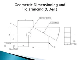
Geometric Dimensioning and Tolerancing (GD&T). What is Geometric Dimensioning and Tolerancing and why use it?.

E N D
What is Geometric Dimensioning and Tolerancing and why use it? • Geometric Dimensioning and Tolerancing is the process of applying standard, international symbols rules and conventions to engineering drawings to control the Form, Profile, Orientation, Position or Run out of a feature or features of a component in addition to limits of size. • Reasons for use are: • Ensures Interchangeability of mating parts. • Saves time during manufacturing/Assembly process. • Aids the inspection process with standardised easy to understand drawings • Alleviates the need for additional notes on drawings
Background of GD&T • Considered a mathematical language and very precise • Describes components in three dimensions similar to Cartesian coordinate system developed by Rene Descartes • Rene Descartes established three precepts about the way we should examine things • Most important being “Never accept anything for true which you do not clearly see to be so”. • This led to idea of examining everything in relation to what it should be “Exact and Perfect” • Cartesian Coordinate system (looking at coordinate planes to describe position of objects) was developed from this. • Looking at components from this perspective led to standards used today • ASME (American Society of Mechanical Engineering ASME Y14.5 and ISO (International Organisation for Standards ISO 1101
Straightness • Straightness is two dimensional tolerance. • The edge must remain within two imaginary parallel lines to meet tolerance. • The distance between the lines is determined by the tolerance size • Rectangular parts usually have a straightness tolerance, it can also be applied to the axis or edge of a cylinder
Flatness • Flatness is a three dimensional version of straightness tolerance. • The surface must remain within two imaginary perfectly flat perfectly parallel planes. • Only the surface not the entire thickness is referenced to the planes. • If used as a primary datum flatness must be specified
Circularity (Roundness) • Circularity is a two dimensional tolerance. • Any two dimensional cross section of a round feature must remain within the tolerance zone created by two concentric circles. • Is Applied to cylinders, cones and Spheres
Cylindricity • Cylindricity specifies the roundness of a cylinder along its entire length. • All cross-sections of the cylinder must be measured together, so cylindricity tolerance is only applied to cylinders. • Circularity and cylindricity cannot be checked by measuring various diameters with a micrometer. • Part must be rotated in a high-precision spindle. Best method would be to use a Coordinate Measuring Machine (CMM).
Profile of a line • The profile of a line is a two dimensional tolerance. • It requires the profile of a feature to fall within two imaginary parallel lines that follow the profile of the feature.
Profile of a Surface • Profile of a Surface is three-dimensional version of the line profile. • Often applied to complex and curved contour surfaces such as aircraft and automobile exterior parts. • The tolerance specifies that the surface must remain within two three dimensional shapes.
Angularity • A three dimensional tolerance. • Shape of the tolerance zone depends on the shape of the feature. • If applied to flat surface, tolerance zone becomes two imaginary planes, parallel to the ideal angle. • If applied to a hole, it is referenced to an imaginary cylinder existing around the ideal angle and center of the hole must stay within that cylinder.
Perpendicularity and Parallelism • Three-dimensional tolerances that use the same tolerance zones as angularity. • Difference is that parallelism defines two features that must remain parallel to each other, while perpendicularity specifies a 90-degree angle between features.
Position • Position is one of the most common location tolerances. • Is a three dimensional related tolerance. • Usually involves more than one datum to establish position of feature. • Does not rely on size shape or angle is concerned with position. • In the case of holes, the tolerance involves the center axis of the hole and must be within the imaginary cylinder around the intended true position of the hole. • If toleranced feature is rectangular, the zone involves two imaginary planes at a specified distance from the ideal true position.
Concentricity and Symmetry • Concentricity and Symmetry are both three-dimensional tolerances. • Concentricity is not commonly measured. • It relates a feature to one or more other datum features. • This shaft is measured in multiple diameters to ensure that they share a common center-axis.
Concentricity and Symmetry • Symmetry is much like concentricity. • Difference is that it controls rectangular features and involves two imaginary flat planes, much like parallelism. • Both symmetry and concentricity are difficult to measure and increase costs of inspection. • When a certain characteristic, such as balance, is important, these tolerances are very effective.
Circular and Total Runout • Circular and Total Runout are three-dimensional and apply only to cylindrical parts. • Both tolerances reference a cylindrical feature to a center datum-axis, and simultaneously control the location, form and orientation of the feature. • Circular runout can only be inspected when a part is rotated. • Calibrated instrument is placed against the surface of the rotating part to detect the highest and lowest points. • The surface must remain within two imaginary circles, having their centers located on the center axis.
Circular and Total Runout • Total Runout is similar to circular runout except that it involves tolerance control along the entire length of, and between, two imaginary cylinders, not just at cross sections. • By default, parts that meet total runout tolerance automatically satisfy all of the circular runout tolerances. • Runout tolerances, especially total runout, are very demanding and present costly barriers to manufacturing and inspection.
Affect of Variation of Form • The diagram below demonstrates how variation of form can affect the fit of a component at maximum material condition.
Datums • Components can have many datum's each considered to have perfect geometric form. • Datum’s can be: • Straight lines • Circles/Holes • Flat planes • Spheres • Cylinders • Cones or a single point some are shown opposite. • Utilising datum's as a reference gives tolerances a new meaning
Datum Reference Frames • Engineering, manufacturing, and inspection all share a common “three plane” concept (Cartesian Coordinate system ) • These three planes are: • Mutually perpendicular • Perfect in dimension and orientation • Positioned exactly 900 to each other. • This concept is referred to as the Datum Reference Frame (DRF)
Datum Reference Frames • The Diagram opposite shows how a rectangular part fits into the corners represented by the inter-section of the three datum planes. • The most important concept to grasp is that when the part is placed into inspection apparatus, it must make contact with the apparatus planes in the order specified by the feature control frame. (Primary, then secondary, then tertiary). This is the only way to assure uniformity in the measurement of different parts.
Datum Reference Frames • A cylindrical part rests on the flat surface of the primary plane and the center of the cylinder aligns with the vertical datum axis created by the intersection of the planes. • In this case, it becomes very important to be able to establish the exact center of the part, whether it is the center of a solid surface, or the center of a hole. • Cylindrical parts are more difficult to measure.