Download
1 / 12
120 likes | 254 Views
Understand the fundamental concepts of working drawings, assembly drawings, parts list, detail drawings, and drawing notes. Learn about design layout and effective communication of design information for production. Develop skills to create a comprehensive family of working drawings.

E N D
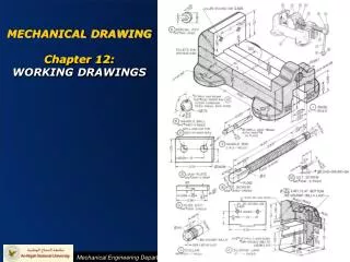
PDT176 COMPUTER-AIDED DRAFTING CHAPTER 6 WORKING DRAWING
CONTENT • Basic Concept of Working Drawing • Assembly Drawing • Parts List • Detail Drawing • Drawing Notes • Design Layout • Summary
7.1 Basic Concept of Working Drawing • An engineered product must have models, drawings, and sketches that document initial design solutions, represent results of analysis, and communicate the final design for production. • Production drawings or working drawings are specialized engineering drawings that provide the information required to produce the part or assembly of the final design. • Working drawings rely on orthographic projection and many other graphical techniques to communicate design information for production. • Engineering drawings are used to communicate designs to others, document design solutions, and communicate design production information. • Documenting is the process of communicating and archiving design and manufacturing information on a product or structure. The documents created include drawings, models, change orders, memos, and reports.
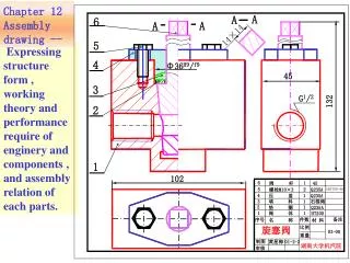
7.2 Assembly Drawing • Assembly drawings show how objects fit together. • All information necessary to complete the assembly must be included on the drawing. • Specific information about the internal surfaces of objects that make up the assembly can be found on the detail drawings of the individual objects.
7.2 Assembly Drawing • Assemblies should be shown in their natural or neutral positions.
7.3 Parts List • Parts list also known as Bill of Materials (BOM). • A parts list is a listing of all parts used on an assembly. • Example of a parts list:
7.3 Parts List • Parts lists may be located on an assembly drawing above the title block or on a separate sheet of paper. • Assembly drawings done using AutoCAD often include the parts list on a separate layer within the drawing. Use only capital letters on a parts list.
7.4 Detail Drawing • A detail drawing is a drawing of a single part. • The drawing should include all the information necessary to accurately manufacture the part, including orthographic views with all appropriate hidden lines, dimensions, tolerances, material requirements, and any special manufacturing requirements.
7.5 Drawing Notes • Drawing notes are used to provide manufacturing information that is not visual, for example, finishing instructions, torque requirements for bolts, and shipping instructions.
7.6 Design Layout • A design layout is not a drawing. It is like a visual calculation sheet used to size and locate parts as a design is developed. A design layout allows you to “build the assembly” on paper.
7.7 Summary • Students should be able to create a family of working drawings including an assembly drawing with assembly numbers assigned and cross reference via the BOM to detail drawings of the parts. • They should also know what a revision block is and how a release block works.