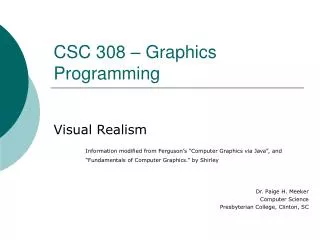
Chapter 1: Graphics Systems and Models
440 likes | 678 Views
Chapter 1: Graphics Systems and Models. Instructor: Shih- Shinh Huang. www.themegallery.com. Outlines. Introduction Image Formation Programmer Interface Graphics Architecture. Introduction. What is Computer Graphics?

Chapter 1: Graphics Systems and Models
E N D
Presentation Transcript
Chapter 1: Graphics Systems and Models Instructor: Shih-Shinh Huang www.themegallery.com
Outlines • Introduction • Image Formation • Programmer Interface • Graphics Architecture
Introduction • What is Computer Graphics? • Concern with all aspects of producing pictures or images using computer. where did this image come from?
Introduction • Applications • Information Display : Graphics for Scientific, Engineering, and Medical Data Nebula Medical Image
Introduction • Applications • Design :Graphics for Engineering and Architectural System AutoCAD 2002 Interior Design
Introduction • Applications • Simulation and Animation: Computer-Generated Models of Physical, Financial and Economic Systems for Educational Aids Flight Simulator Mars Rover Simulator
Introduction • Applications • User Interfaces : Graphics for Artist Painter
Introduction • Applications • Entertainment: Graphics for Movie, Game, VR Final Fantasy Online Game
Introduction • Graphics System Output device Input devices Image formed in FB
Introduction • Graphics System • Input Devices • The system is usually equipped with pointing devices (location +buttons). • The common devices are mouse, joystick, and data tablet. • Data gloves or computer vision system can provide higher-dimensional data.
Introduction • Graphics System • Input Devices
Introduction • Graphics System • Input Devices
Introduction • Graphics System • Processors • In a simple system, there are only one processor for normal processing and graphical processing. • Today, all graphics system are characterized by special-purpose graphical processing unit (GPU) • It takes charge of a conversion of geometric entities to pixel in the frame buffer (Rasterization).
Introduction • Graphics System • Pixels • An image is produced as an array (raster) of picture elements (pixel). column row
Introduction • Graphics System • Frame Buffer • It is a part of memory to store the set of pixels. • It is usually implemented with special type of memory chips to enable redisplaying. • Resolution: the number of pixels in frame buffer • Depth or Precision: the number of bits used for each pixel.
Introduction • Graphics System • Output Device • The general display is cathode-ray tube (CRT)
Image Formation • Description • Image formation is a process analogous to how images are formed by physical systems • Human Visual System • Camera • The process combining the specification of objects with viewers to produce 2D image. • Object is an entity existing in space independent of any image-formation process and any viewer. • Viewers is a way to from images from objects.
Image Formation Object Camera View Images seen by three different views
Image Formation • Light Description • Light is a form of electromagnetic radiation • Wavelengths • Frequencies • The wavelengths in the range of 350 (nm) to 780 nm is called visible spectrum
Image Formation • Pinhole Camera Model • A pinhole camera is a box with a small hole in the center of one side. • The film is placed inside the box on the side opposite the pinhole
Image Formation • Pinhole Camera Model • Point Projection
Image Formation • Pinhole Camera Model • Field or View of Angle • The angle made by the largest object that our image can image on its film plane.
Image Formation • Pinhole Camera Model • Depth of Field • The longest distance that the objects can appear on its film plane. • The ideal pinhole camera model has an infinite depth of field. • Limitations • The pinhole is so small that it admits only a single ray from a point source • The camera cannot be adjusted to have different angle of view.
Image Formation • Human Visual System 視網膜上兩種視覺接受器: • 錐細胞錐細胞(cone): 6~7 million • 桿細胞桿細胞(rod):75~150 million
Image Formation • Human Visual System 人類的視覺神經路徑人類的視覺神經路徑 網膜→視交叉→側膝核→視皮質網膜→ 視交叉→側膝核→視皮質
Image Formation • Synthetic-Camera Model • The image plane is moved in front of camera. • The limitation of field can be expressed by placing a clipping window. Clipping Window Center of Projection (COP) Projection Plane
Programmer Interface • Description • There are numerous ways that a user can interact with a graphics system. • A user develops images through interactions with display using input devices. • Someone develops the code for the application
Programmer Interface • API Functions • It is to provide interfaces between an application program and a graphics system. • API in OpenGL • It is to specify how to form an image: (1) Objects, (2) Viewer, (3) Light Source(s), (4) Materials • The APIs provided by OpenGL is based on the synthetic-camera model.
Programmer Interface • Objects • Objects are usually defined by sets of vertices • Most APIs provide sets of primitive objects (primitives) for the user. • Points (0D object) • Line segments (1D objects) • Polygons (2D objects) • Some curves and surfaces • OpenGL programs define primitives through lists of vertices.
Programmer Interface • Example type of object location of vertex glBegin(GL_POLYGON) glVertex3f(0.0, 0.0, 0.0); glVertex3f(0.0, 1.0, 0.0); glVertex3f(0.0, 0.0, 1.0); glEnd( ); end of object definition
Programmer Interface • Example • glBegin() and glEnd()brackets the calls to define the object to be drawn. • OpenGL Commands • Prefix: gl • Initial capital letters for each word • Optional Character: number of arguments or type • OpenGL Constants • Prefix: GL • All characters are capitilized • Underscores among Words. glVertex3f(0.0, 0.0, 0.0); • glBegin(GL_POLYGON)
Programmer Interface • Viewer • Available APIs differ in how much flexibility in camera selection. • Camera Specifications • Position • Orientation • Focal Length • Film Plane.
Programmer Interface • Light • Point sources v.s distributed sources • Spot lights • Near and far sources • Color properties • Material Properties • Absorption: color properties • Scattering
Graphics Architecture • General Description • Two Sides of API • Application Program • Combination of hardware and software that implements the functionality of the API. • Various approaches are to develop graphics architectures for supporting graphics APIs.
Graphics Architecture • Early Graphics System • It used general-purposed computers characterized by a CPU. • CPU Task • Run the application program • Compute the endpoints of line segment.
Graphics Architecture • Display Processors • The display processors include instructions to display primitives. • The display primitives are stored in its own memory denoted as display list.
Graphics Architecture • Pipeline Architecture • The creation of special-purpose VLSI chips enables the pipeline technology. • The pipeline is workable in graphics because it processes data in the same manner. • For two stage pipeline, the throughput of the system has been doubled. a+(b*c)
Graphics Architecture • Scene Geometry • Scene geometry is the collection of primitives and vertices. • A scene consists of a set of objects. • Each object comprises a set of primitives. • A primitive comprises a set of vertices. • In a complex scene, there are may be thousands of vertices. • We must process all these vertices in a similar manner to form an image in the frame buffer.
Graphics Architecture • Graphics Pipeline • The imaging processing includes four steps. • Vertex Processing • Clipping and Primitive Assembly • Rasterization • Fragment Processing • These four steps can be performed in a pipeline manner.
Graphics Architecture • Vertex Processing • Coordinate Transformation: imaging process is a transformation between different coordinate system. • Vertex Coloring • Program Specification • Computation from a realistic shading model.
Graphics Architecture • Clipping and Primitive Assembly • Determine thearea in the world that can be seen by the camera. • Clipping Volume • The projection in this volume appear in the image. • Those that are outside are to be clipped out. • The clipping is done in primitive level rather than vertex level. • The output of this stage is a set of primitives whose projections can appear in the image.
Graphics Architecture • Clipping and Primitive Assembly 2D Clipping Volume 3D Clipping Volume
Graphics Architecture • Rasterization(Drawing) • It converts the primitives in terms of vertices to pixels in the frame buffer. • The output is a set of fragments for each primitive, that is, pixel with color or location • Fragment Processing • It takes the generated fragments to update the pixels in the frame buffer. • The pixels in frame buffer can be read to blend with the fragment.