Download
1 / 9
90 likes | 200 Views
Explore the mechanism used for launching payloads onto the moon's surface, step-by-step deployment explained.

E N D
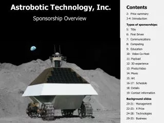
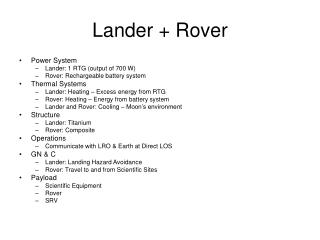
CCR Payload for the Astrobotic Lander 30 March 2011 --------------------------------------------Kris Zacny, PhDVice PresidentDirector, Technology Exploration GroupHoneybee Robotics Spacecraft Mechanisms Corporation 398 W Washington Blvd., Suite 200, Pasadena, CA 91103ph: 626-389-8459 / fax: 626-689-4823 / mob: 510-207-4555 / blackberry: 646-508-9807 zacny@honeybeerobotics.comhttp:/www.honeybeerobotics.com
CCR System CCR Deployment Mechanism
CCR Deployment Mechanism in stowed position Pin Puller #1 is actuated, releasing the spring loaded linear stage Linear stage is on rollers for smooth deployment CCR Deployment Sequence [1] 1 Rover track and landing thrusters hidden for clarity
CCR Deployment Sequence [2] • Linear stage reaches end of travel • Roller (1) constraining CCR is free, due to slot in roller track (2) • Preloaded, redundant torsion springs (3) cause CCR rod to pivot upwards 3 1 2
CCR Deployment Sequence [3] • Pivot Assembly reaches hard stop. Limit switch is triggered • Pin Puller #2 is actuated, releasing the CCR Rod 2
2 3 1 4 CCR Deployment Sequence [4] • Nose Cone (3) contacts ground • Puncture Rod (2) is pushed upwards. Tip punctures sealed gas cylinder (1) • Gas is released from gas cylinder, exiting out the nose cone jets (4) • CCR Rod plunges into the soil CCR Rod is free to slide within the sleeve
CCR Deployment Sequence [5] • (Left) Non-contact position sensor is triggered at end of travel • (Center) Pin Puller #3 is actuated, releasing spring loaded arms simultaneously • (Right) CCR Rod continues to plunge into soil unhindered 3 3
CCR Deployed [2] ~39”