The OSI Model
560 likes | 600 Views
Learn about the OSI Model, layering concept, open vs proprietary standards, communication layering, and more in computer networks. Explore this fundamental framework deeply.

The OSI Model
E N D
Presentation Transcript
The OSI Model Based on Computer Networks and Internets (Comer)
OSI or ISO • The layering model is OSI, which stands for Open System Interconnection. • The organization that developed the model is ISO, International Organization for Standardization. • ANSI (American National Standards Institute) is a member of ISO. • ANSI farms out much of the hardware standardization to the IEEE.
ISO • International Organization for Standardization, shouldn’t that be IOS??? • No. ISO is not really an acronym. • “ISO” was chosen because it means equal as in an isosceles triangle that has two equal sides.
Standards • “Standards are documented agreements containing technical specifications or other precise criteria to be used consistently as rules, guidelines, or definitions of characteristics, to ensure that materials, products, processes and services are fit for their purpose.” • From the ISO website
Open versus Proprietary • Open: specifications are public. • Requires committee agreement, can be slow. • Proprietary: Privately owned and controlled, specifications are kept private so that other companies cannot duplicate. • No outside agreement needed, can be reactive (faster). • Consumers prefer open and standardized systems, as these allow them to use the products of various manufacturers. • But sometimes it takes too long to come up with them.
Layering/Interfacing • Layering is an important concept in computing. • When a user runs an application, • The user interfaces with the application. • The application interfaces with the operating system. • The operating system interfaces with the BIOS. • The BIOS interfaces with the input/output hardware.
To what purpose? • The user need only know something about the application and doesn’t need to know any details about the operating system, the BIOS or the hardware. • Similarly the application needs information about the user and the operating system but not the BIOS or hardware. • For layering to be successful there must be a “standard” interface into a layer. • The operating system is said to provide an Application Programming Interface (API).
More than just a way of thinking about it • These layers can be seen in the industry, there are • Companies that specialize in hardware • Seagate, Maxtor, Western Digital • Companies that specialize in BIOS • AMI, Phoenix • Companies that specialize in operating systems • Microsoft, Sun, B • Companies that specialize in applications • Oracle, Microsoft, Google
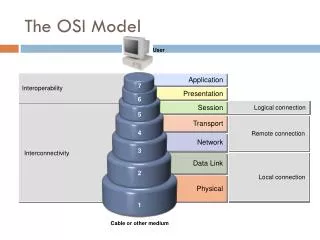
Communications Layering • The communication between two (or more) users on a network similarly is broken down into layers. • A possible model for this layering was laid out by the ISO.
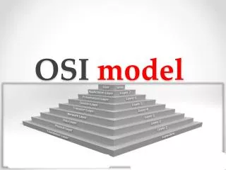
What is OSI? • OSI serves as a "reference model" for how information is transmitted between any two points in a network. • It guides manufacturers (a.k.a. vendors) so they can make products that will work with other products. • The OSI model is comprised of seven layers that are involved in communicating between two nodes of a network.
It’s not the law • The OSI model was never adopted as a rigorous set of specifications. • The lower layers (physical, data link, network and transport) are for the most part adhered to. • What’s really used is the TCP/IP model
Classroom not boardroom • Many vendors agreed at one time or another to adhere to OSI, however, the system proved to be too loosely defined, overly broad and the companies had much invested in their proprietary standards. • Some products like X.400 (an e-mail system used mainly in Europe and Canada, an alternative to SMTP) adhere to OSI. • But mainly OSI has become a teaching tool.
OSI’s Purpose • Even if manufacturers do not restrict themselves to a particular OSI layer, they usually think of and describe their products in relationship to the OSI model. • It provides a language and framework for discussion of networks, so it persists and continues to be taught.
TCP/IP model • Another model for understanding communications networks is the TCP/IP model. • It also is broken into layers • It has no equivalent of the OSI model’s physical layer. • The next three layers of the OSI model and the TCP/IP model are roughly equivalent. • The top three layers of the OSI model are combined into one layer in the TCP/IP model.
The main idea • The communication between computers can be broken down into layers. • Each layer is characterized by its functions and how it interfaces with the adjacent layers. • Within the source’s computer and starting at the user level, the communication is passed down through the layers to the lowest layer where it is sent through some transmission medium.
The main idea (Cont.) • The communication travels at the lowest layer (physical), occasionally rising up to the second layer (bridge) or third layer (router) until it reaches the destination. • The communication now passes up through the layers.
The main idea (Cont.) • The layers are realized by a combination of the operating system, applications (for instance a browser), network protocols such as TCP/IP, and the software and hardware that actually place a physical signal onto a transmission line (NIC, modem, etc) • Don’t confuse TCP/IP (the stack, model) with layer protocols TCP (layer 4) and IP (layer 3).
OSI: Network / Computer • The Transport layer can be viewed as the division between the computer and the network. • The lowest three layers (physical, data link and network) deal with “a best effort” to get information to the desired computer. • The Transport layer verifies the effort, and hides the network from the layers above. • The remaining layers treat the data as if it was local.
Layer 1: Physical • There is no interpretation at this level, a stream of 1’s and 0’s are put into a form convenient for transmission. • Waves (with little regard for their information content) are sent and received. • This level is the most hardware oriented. It includes specifications about • NIC card speeds • Types and lengths of cable • Voltage characteristics (range, level or edge) • Etc.
Physical Layer (Cont.) • The physical layer involves protocols for actual transmission • Ethernet • FDDI • RS232 • ATM • These protocols also involve the interface with the next higher layer.
Layer 2: The data-link layer • At this layer one begins to consider bytes instead of just bits, one examines some of the information content of the signal (at least the address and some of the error detection sequencing) • Bridges operate at this level • They know where a packet is headed. • They know whether or not it has been involved in a collision.
Data Link (Cont.) • Data packets are encoded and decoded into bits. • It directs packets and handles errors from the physical layer. • It handles synchronization (timing). • It must know where one bit ends and the next one begins. • It must know where one byte ends and the next one begins.
Data link sublayers • The data link layer is divided into two sublayers: • The MAC (Media Access Control) sublayer: takes the signal from or puts the signal onto the transmission line (“touches” physical layer). • The LLC (Logical Link Control) sublayer: starts to interpret the signal as data, includes timing (synchronization) and error checking.
Layer 3: The network layer • The router acts at this layer. • One of the main functions of the layer is routing. Store and forward are network layer functions. • Building the routing tables, troubleshooting the routing tables when there is a lot of traffic or if a connection goes down. • The network layer also gathers related packets (packet sequencing).
Layer 4: The transport layer • As stated before, Layer 4 is the dividing line between inter-computer transactions and intra-computer transactions. • Layer 4 manages end-to-end verification. • The lower layers make a “best effort” but if data is lost, so be it. Layer 4 must ensure that the information was received intact. • It does a higher-order error-checking. • The transfer should be “transparent.” The higher layers do not know the data came from another computer.
Whose job is it? • At a node Layer 3 collects associated packets if one was dropped it may throw them all away. • It is the responsibility of the source’s Layer 4 to look for some acknowledgement that all packets arrived. If no acknowledgment is received, it should retransmit.
Layer 5: The session layer • Within connection-oriented schemes, we have a notion of a “session.” • It is an agreement between a source and destination to communicate. • This layer establishes, manages and terminates sessions between applications (they could be on the same computer or on different computers).
Layer 6: The presentation layer • This layer provides independence from differences in data representation (e.g., encryption) by translating from application to network format, and vice versa. • The presentation layer works to transform data into the form that the application layer can accept. This layer formats and encrypts data to be sent across a network, providing freedom from compatibility problems. It is sometimes called the “syntax layer.”
Layer 7: The application layer • This layer supports application and end-user processes. • Communication partners are identified, quality of service is identified, user authentication and privacy are considered, and any constraints on data syntax are identified.
Layer 7: The application layer • Everything at this layer is application-specific. This layer provides application services for file transfers, e-mail, and other network software services. Telnet and FTP are applications that exist entirely in the application level. • These are not applications (like Word and Excel) but services for such applications!
Mnemonic • Please Do Not Throw Sausage Pizza Away • Please Physical • Do Data Link • Not Network • Throw Transport • Sausage Session • Pizza Presentation • Away Application
OSI in real life • For example, TCP/IP is usually packaged with other Internet programs as a suite of products that support communication over the Internet. This suite includes the File Transfer Protocol (FTP), Telnet, the Hypertext Transfer Protocol (HTTP), e-mail protocols, and sometimes others. • Although TCP fits well into the Transport layer of OSI and IP into the Network layer, the other programs fit rather loosely (but not neatly within a layer) into the Session, Presentation, and Application layers.
Layered Software • In order to communicate on a network, each computer must have software that passes packets from layer to layer. Each layer only communicates with its neighbors. • The entire package of software for moving through layers may be called a “suite” or a “stack.” • “What stack are you running?” • The most widely used communication stack is TCP/IP.
Multiple protocol stacks • One computer may communicate with different computers using different protocols across the SAME physical medium. • The information that identifies which protocol is being used are contained within the frames.
An Ethernet Frame type field identifies what kind of information is contained within and how it should be handled.
Nested Headers • As a source computer passes a message down through the protocol stack, each layer adds a header. • The header added at a particular layer is intended for the corresponding layer on the destination computer. • Thus the message passed down from Layer X to Layer Y on the source computer should be the same as the message passed up from Layer Y to Layer X on the destination computer.
Layer-to-Layer • Because source Layer Y added the header that destination Layer Y strips off, this is effectively a Layer-Y-to-Layer-Y communication (even though it passes through other lower layers). • For instance, the source and destination presentation layers have to negotiate the format of the data • Will it be text? Will it be encrypted? • There is no direct link between presentation layers, the information passes down through the physical layer; nevertheless, the two layers do communicate.
Nested Headers (Fig. 16-4) and trailer Layer 2 also adds a trailer
No physical layer header • The physical layer does not add a header. • Headers contain information needed by the layers. • The physical layer does not operate at an “information” level.
What’s the point? • The purpose of belonging to a network is for computers to communicate — an exchange of information. • The information must get where it’s going – addressing is important to networking. • If that information is incorrect or not trustworthy, then there is no gain. Thus error detection and correction (usually through retransmission) are a vital part of networking. • Another issue is that one has to know what to do with the information once it arrives – types play a role.
Single packet and Multi-packet • In a packet-switching scheme, the information being exchanged is transmitted in sequences of packets. • Consequently error detection must take place on two basic levels • Within an individual packet • Within a group of related packets
Single Packet Techniques • This sort of detection tends to take place at Layer 2, the Data Link Layer. • The standard techniques are: • Parity bits • Checksums • Cyclic Redundancy Checks
Multi-Packets Techniques • The original information is broken down into a sequence of packets or cells. • To reconstruct the information, the receiver must know the number of packets expected to arrive and the order they should be placed in. • In a “connectionless scheme”, packets might be lost or arrive out-of-order. • Multi-packet error detection/correction is handled in Layers 3 and 4 (Network and Transport).
Sequencing 1 of 4 2 of 4 3 of 4 4 of 4
Various Problems • The protocol stack must be able to deal with the various scenarios that might arise • A packet might be lost along the way. • A packet might arrive corrupted. • If corrupted, Layer 2 will throw the packet away, so as far as Layer 3 and higher are concerned, corrupted and lost are the same. • There are more losses due to congestion than corruption due to hardware failure.