Single-cycle CPU Control Logic Guide
Learn how to decode and control the registers, ALU operations, opcodes, and primary ALU functions for a single-cycle CPU design. Understand how instructions are decoded to set up the datapath efficiently.

Single-cycle CPU Control Logic Guide
E N D
Presentation Transcript
Chapter 5b: Single-cycle CPU Control
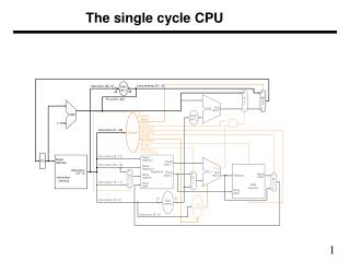
Registers Read reg. num A Read reg num A Read reg data A Read reg num B Write reg num Read reg data B Write reg data What do we need to control? Mux - are webranching or not? Registers- Should we write data? 0 4 Result 1 Mux - Result fromALU or Memory? Add Result Sh.Left2 Add Read address Data Memory Read address PC Zero Read data 1 Instruction [31-0] Write address Result InstructionMemory 0 0 Write data 1 16 32 signextend Mux - Wheredoes 2nd ALUoperand come from? Memory-Read/Write/neither? ALU -What is theOperation? Almost all of the information we need is in the instruction! 5.3
OpcodeRSRTRDShAmtFunction OpcodeRSRTImmediate Data OpcodeImmediate Data Instructions – Opcode and Function Code R-Type I-Type J-Type Main instruction info is in the Opcode, which can be used to set up the datapath and the primary ALU (for I- and J-types) For R-type instructions, the Function Code determines the function of the primary ALU (add, sub, mul, div, slt, and, or, etc.) 5.3
31-26 25-21 20-16 15-11 10-6 5-0 OpcodeRSRTRDShAmtFunction 31-26 25-21 20-16 15-0 OpcodeRSRTImmediate Data Decoding the Instruction - Data The instruction holds the key to all of the data signals R-type To ctrllogic Readreg. A Readreg. B Writereg. To ALUControl Not Used Memory,Branch To ctrllogic Readreg. A Writereg./Readreg. B Memory address or Branch Offset One problem - Write register number must come from two different places. 5.3
Registers Read reg. num A Read reg num A Read reg data A Read reg num B Write reg num Read reg data B 0 Write reg data 1 We can decode the data simply by dividing up the instruction bus Instruction Decoding 0 Opcode: [31-26] 4 Result 1 Add Result Sh.Left2 Add Op:[31-26] Ctrl Rs:[25-21] Read address Rt:[20-16] Data Memory Read address PC Zero Read data 1 Instruction [31-0] Write address Result InstructionMemory 0 0 Write data Rd:[15-11] 1 Read Reg A: Rs Imm:[15-0] 16 32 signextend Read Reg B: Rt Write Reg: Either Rd or Rt Immediate Data: [15-0] 5.3
Registers Read reg. num A Read reg num A Read reg data A Read reg num B Write reg num Read reg data B 0 Write reg data 1 Control Signals 0 4 1:LW,R-type0:SW,Branch 1: Branch taken 0:Others Result 1 Add Result Sh.Left2 PCSrc Add Op:[31-26] 1:SW0:others 1:LW0:others Ctrl MemWrite RegWrite MemToReg ALUSrc Rs:[25-21] Read address Rt:[20-16] Data Memory 1: Memory0: R-type,Branch Read address PC Zero Read data 1 Instruction [31-0] Write address Result InstructionMemory 0 0 Write data Rd:[15-11] 1 RegDest 1:R-type 0:I-type Imm:[15-0] MemRead 16 32 signextend ? 1: LW 0: Others 5.3
Operation A Zero Result OverFlow B Cout The Primary ALU • The Primary ALU is right in the middle of everything... • It must: • Add, Subtract, And, Or, etc. for R-types (from FC) • Subtract for a BEQ (from Opcode) • Add to determine address for a LW, SW (from Opcode) Function Operation Result And 000 R = A • B Or 010 R = A Ú B Add 100 R = A + B Subtract 101 R = A - B SLT 111 R = 1 if A < B 0 if A ³ B 5.3
Setting the ALU controls Main Control Logic generates ALUOp signal00: ALU adds01: ALU subtracts10: ALU looks at F.C.11: Unused • The instruction Opcode and Function give us the info we need • For R-type instructions, Opcode is zero, function code determines ALU controls • For I,J-type instructions, Opcode determines ALU controls Instruction Opcode ALUOp Funct. Code ALU action ALU controladd 000000 10 100000 add 100 sub 000000 10 100010 subtract 101 and 000000 10 100100 and 000 or 000000 10 100101 or 010 SLT 000000 10 101010 SLT 111 load word 010011 00 xxxxxx add 100 store word 011011 00 xxxxxx add 100 branch equal 000100 01 xxxxxx subtract 101 5.3
Registers Read reg. num A Read reg num A Read reg data A Read reg num B Write reg num Read reg data B 0 Write reg data 1 6 ALU Control Signals 0 4 Result 1 Add Result Sh.Left2 PCSrc Add Op:[31-26] Ctrl MemWrite RegWrite MemToReg ALUSrc Rs:[25-21] Read address Rt:[20-16] Data Memory Read address PC Zero Read data 1 Instruction [31-0] Write address Result InstructionMemory 0 0 Write data Rd:[15-11] 1 RegDest Imm:[15-0] 00: Add01: Sub10: R-type ALUCtrl MemRead 16 32 signextend FC:[5-0] ALUOp ALU Control - A function of: ALUOp and the function code 5.3
Inside the control oval 00:Mem01:Branch10:R-type 1:Mem0:ALU 0:Reg1:Imm • This control logic can be decoded in several ways: • Random logic, PLA, PAL • Just build hardware that looks for the 4 opcodes • For each opcode, assert the appropriate signals 0:Rt1:Rd 1:Branch Reg ALU Mem Reg Mem Mem Instruction Opcode Write Src To Reg Dest Read Write PCSrc ALUOp R-format 000000 1 0 0 1 0 0 0 10 LW 100011 1 1 1 0 1 0 0 00 SW 101011 0 1 x x 0 1 0 00 BEQ 000100 0 0 x x 0 0 1 01 Note: BEQ must also check the zero output of the ALU... 5.3
We must ANDBEQ and Zero Registers Read reg. num A Read reg num A Read reg data A Read reg num B Write reg num Read reg data B 0 Write reg data 1 6 Control Signals 0 4 Result 1 Add Result Sh.Left2 Add PCSrc BEQ Ctrl MemToReg MemRead MemWrite Op:[31-26] ALUOp ALUSrc RegWrite RegDest Rs:[25-21] Write Read Read address Rt:[20-16] Data Memory Read address PC Zero Read data 1 Instruction [31-0] Write address Result InstructionMemory 0 0 Write data Rd:[15-11] 1 Imm:[15-0] ALUCtrl 16 32 signextend FC:[5-0] 5.3
32 1 28 26 0 4 Registers Read reg. num A Read reg num A Read reg data A Read reg num B Write reg num Read reg data B 0 Write reg data 1 6 Jumping Sh.Left2 Concat. 0 4 Result 1 [31-28] Add Result Sh.Left2 PCSrc Add Jump J:[25-0] BEQ Ctrl MemToReg MemRead MemWrite Op:[31-26] ALUOp ALUSrc RegWrite RegDest Rs:[25-21] Write Read Read address Rt:[20-16] Data Memory Read address PC Zero Read data 1 Instruction [31-0] Write address Result InstructionMemory 0 0 Write data Rd:[15-11] 1 Imm:[15-0] ALUCtrl 16 32 signextend FC:[5-0] 5.3
Performance What major functional units are used by different instructions? R-type: Instr. FetchRegisterReadALURegisterWrite 6ns LW: Instr. FetchRegisterReadALUMemory ReadRegisterWrite 8ns SW: Instr. FetchRegisterReadALUMemory Write 7ns Branch: Instr. FetchRegisterReadALU 5ns Jump: Instr. Fetch 2ns Assume the following times: Since the longest time is 8ns (LW),the cycle time must be at least 8ns. Memory Access: 2ns ALU: 2ns Registers: 1ns