Series-Parallel Circuits
Series-Parallel Circuits. OBJECTIVES. Learn about the unique characteristics of series-parallel configurations and how to solve for the voltage, current, or power to any individual element or combination of elements.


Series-Parallel Circuits
E N D
Presentation Transcript
OBJECTIVES • Learn about the unique characteristics of series-parallel configurations and how to solve for the voltage, current, or power to any individual element or combination of elements. • Become familiar with the voltage divider supply and the conditions needed to use it effectively. • Learn how to use a potentiometer to control the voltage across any given load.
INTRODUCTION • A series-parallel configuration is one that is formed by a combination of series and parallel elements. • A complex configuration is one in which none of the elements are in series or parallel.
FIG. 7.1 Series-parallel dc network. SERIES-PARALLEL NETWORKS
FIG. 7.2 Introducing the reduce and return approach. REDUCE AND RETURN APPROACH
FIG. 7.3 Series-parallel network for Example 7.1. FIG. 7.4 Substituting the parallel equivalent resistance for resistors R2 and R3 in Fig. 7.3. REDUCE AND RETURN APPROACH
FIG. 7.5 Series-parallel network for Example 7.2. FIG. 7.6 Schematic representation of the network in Fig. 7.5 after substituting the equivalent resistance R for the parallel combination of R2and R3. REDUCE AND RETURN APPROACH
FIG. 7.7 Inserting an ammeter and a voltmeter to measure I4and V2, respectively. REDUCE AND RETURN APPROACH
BLOCK DIAGRAM APPROACH • Once the grouping of elements reveals the most direct approach, you can examine the impact of the individual components in each group. • This grouping of elements is called the block diagram approach
FIG. 7.8 Introducing the block diagram approach. FIG. 7.9 Block diagram format of Fig. 7.3. BLOCK DIAGRAM APPROACH
FIG. 7.11 Reduced equivalent of Fig. 7.10. FIG. 7.10 Example 7.3. BLOCK DIAGRAM APPROACH
FIG. 7.12 Example 7.4. BLOCK DIAGRAM APPROACH
FIG. 7.13 Reduced equivalent of Fig. 7.12. BLOCK DIAGRAM APPROACH
FIG. 7.15 Block diagram of Fig. 7.14. FIG. 7.14 Example 7.5. DESCRIPTIVE EXAMPLES
FIG. 7.16 Alternative block diagram for the first parallel branch in Fig. 7.14. DESCRIPTIVE EXAMPLES
FIG. 7.17 Example 7.6. DESCRIPTIVE EXAMPLES
FIG. 7.18 Block diagram for Fig. 7.17. FIG. 7.19 Reduced form of Fig. 7.17. DESCRIPTIVE EXAMPLES
FIG. 7.20 Example 7.7. DESCRIPTIVE EXAMPLES
FIG. 7.21 Network in Fig. 7.20 redrawn. DESCRIPTIVE EXAMPLES
FIG. 7.22 Example 7.8. DESCRIPTIVE EXAMPLES
FIG. 7.23 Network in Fig. 7.22 redrawn. DESCRIPTIVE EXAMPLES
FIG. 7.26 Example 7.10. DESCRIPTIVE EXAMPLES
FIG. 7.27 Network in Fig. 7.26 redrawn. DESCRIPTIVE EXAMPLES
FIG. 7.28 An alternative approach to Example 7.10. DESCRIPTIVE EXAMPLES
FIG. 7.30 Network in Fig. 7.29 redrawn to better define a path toward the desired unknowns. FIG. 7.29 Example 7.11. DESCRIPTIVE EXAMPLES
FIG. 7.31 Complex network for Example 7.11. DESCRIPTIVE EXAMPLES
FIG. 7.32 Ladder network. LADDER NETWORKS • A three-section ladder network appears in Fig. 7.32. • The reason for the terminology is quite obvious for the repetitive structure. • Basically two approaches are used to solve networks of this type.
FIG. 7.33 Working back to the source to determine RT for the network in Fig. 7.32. LADDER NETWORKS
FIG. 7.34 Calculating RT and Is. FIG. 7.35 Working back toward I6. LADDER NETWORKS
FIG. 7.36 Calculating I6. LADDER NETWORKS
FIG. 7.37 An alternative approach for ladder networks. LADDER NETWORKS
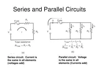
VOLTAGE DIVIDER SUPPLY (UNLOADED AND LOADED) • When the term loaded is used to describe voltage divider supply, it refers to the application of an element, network, or system to a supply that draws current from the supply. • In other words, the loading down of a system is the process of introducing elements that will draw current from the system. The heavier the current, the greater is the loading effect.
FIG.7.38 Voltage divider supply. VOLTAGE DIVIDER SUPPLY (UNLOADED AND LOADED)No-Load Conditions • Through a voltage divider network such as that in Fig. 7.38, a number of different terminal voltages can be made available from a single supply.
VOLTAGE DIVIDER SUPPLY (UNLOADED AND LOADED)No-Load Conditions • In general, for a voltage divider supply to be effective, the applied resistive loads should be significantly larger than the resistors appearing in the voltage divider network.
FIG. 7.39 Voltage divider supply with loads equal to the average value of the resistive elements that make up the supply. VOLTAGE DIVIDER SUPPLY (UNLOADED AND LOADED)Loaded Conditions
FIG. 7.40 Voltage divider supply for Example 7.12. VOLTAGE DIVIDER SUPPLY (UNLOADED AND LOADED)Loaded Conditions
FIG. 7.41 Unloaded potentiometer. POTENTIOMETER LOADING • For the unloaded potentiometer in Fig. 7.41, the output voltage is determined by the voltage divider rule, with RTin the figure representing the total resistance of the potentiometer.
FIG. 7.42 Loaded potentiometer. POTENTIOMETER LOADING
POTENTIOMETER LOADING • In general, when hooking up a load to a potentiometer, be sure that the load resistance far exceeds the maximum terminal resistance of the potentiometer if good control of the output voltage is desired.
FIG. 7.44 Loaded potentiometer with RL >>RT. FIG. 7.43 Loaded potentiometer with RL <<RT. POTENTIOMETER LOADING
FIG. 7.45 Example 7.13. POTENTIOMETER LOADING
FIG. 7.46 Iron-vane movement. AMMETER, VOLTMETER, AND OHMMETER DESIGN
FIG. 7.48 Basic ammeter. FIG. 7.47 Iron-vane movement; (a) photo, (b) symbol and ratings. AMMETER, VOLTMETER, AND OHMMETER DESIGN
FIG. 7.49 Multirange ammeter. AMMETER, VOLTMETER, AND OHMMETER DESIGN
FIG. 7.50 Basic voltmeter. AMMETER, VOLTMETER, AND OHMMETER DESIGN
AMMETER, VOLTMETER, AND OHMMETER DESIGNThe Voltmeter • A variation in the additional circuitry permits the use of the iron-vane movement in the design of a voltmeter. • The 1 mA, 43 Ω movement can also be rated as a 43 mV (1 mA x 43 Ω), 43 movement, indicating that the maximum voltage that the movement can measure independently is 43 mV. • The millivolt rating is sometimes referred to as the voltage sensitivity (VS).
FIG. 7.51 Multirange voltmeter. AMMETER, VOLTMETER, AND OHMMETER DESIGNThe Voltmeter
AMMETER, VOLTMETER, AND OHMMETER DESIGNThe Ohmmeter • In general, ohmmeters are designed to measure resistance in the low, middle, or high range. • The most common is the series ohmmeter, designed to read resistance levels in the midrange.
FIG. 7.52 Series ohmmeter. AMMETER, VOLTMETER, AND OHMMETER DESIGNThe Ohmmeter
FIG. 7.53 Nanovoltmeter. AMMETER, VOLTMETER, AND OHMMETER DESIGNThe Ohmmeter