Download
1 / 66
690 likes | 978 Views
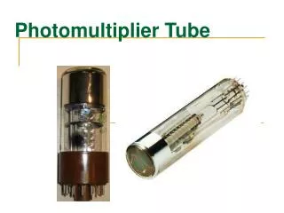
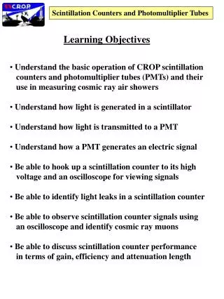
Scintillation Counters and Photomultiplier Tubes. Learning Objectives. Understand the basic operation of CROP scintillation counters and photomultiplier tubes (PMTs) and their use in measuring cosmic ray air showers Understand how light is generated in a scintillator

E N D
Scintillation Counters and Photomultiplier Tubes Learning Objectives • Understand the basic operation of CROP scintillation • counters and photomultiplier tubes (PMTs) and their • use in measuring cosmic ray air showers • Understand how light is generated in a scintillator • Understand how light is transmitted to a PMT • Understand how a PMT generates an electric signal • Be able to hook up a scintillation counter to its high • voltage and an oscilloscope for viewing signals • Be able to identify light leaks in a scintillation counter • Be able to observe scintillation counter signals using • an oscilloscope and identify cosmic ray muons • Be able to discuss scintillation counter performance • in terms of gain, efficiency and attenuation length
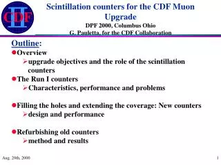
Scintillation Counters and Photomultiplier Tubes Outline • Introduction • Light Generation in Scintillators • Light Collection • Optical Interfaces and Connections • Photodetectors and photomultiplier tubes • Performance and Exercises • References
Scintillation Counters and Photomultiplier Tubes Introduction • Scintillation counters are multi-purpose particle detectors • used in many experimental physics applications • Used for charged particle detection (positive or negative), • but also neutral particles (photons, neutrons), • although light-generation mechanisms are different for • charged and neutral particles • Basic sequence -- light generation by particle passing • through scintillator material, light collection, • photodetector turns light into electric signal • Scintillation Counter Properties • Fast time response -- light generated almost immediately • after particle passes through scintillator, photodetectors • give fast electric signal • Can count number of particles using pulse height. • The larger the signal size, the greater the number of • particles • Position information • Based on size of active scintillator material
Scintillation Counters and Photomultiplier Tubes Basic principles of operation Passage of charged particle generates light in scintillator Charged particle Light guide transmits light to photodetector Photomultiplier tube (PM or PMT) generates electric signal
Scintillation Counters and Photomultiplier Tubes Introduction • Examples from High Energy Physics experiments • at particle accelerators • Hodoscope -- an array of several counters covering • a large area • Veto counters -- for particles you don’t want to • measure • Calorimetry -- measuring a particle’s total energy • Triggering -- a fast signal which indicates an • interesting event to record • Examples from cosmic ray experiments • CASA • KASCADE
Scintillation counters in High-Energy Physics Experiments Fermilab, Batavia, Illinois Protons Anti-protons CERN, Geneva, Switzerland
Scintillation Counters and Photomultiplier Tubes Scintillation counter hodoscope Photomultiplier tube Scintillator wedge Foil wrapping Counters arranged as pizza slices
Chicago Air Shower Array (CASA) Dugway Proving Grounds, Utah • University of Chicago and University of Utah collaboration • to study extended cosmic ray air showers • 1089 boxes in a rectangular grid, 15 meter spacing, each with • 4 scintillator planes and 4 photomultplier tubes • 1 low voltage and 1 high voltage supply • 1 electronics card for data triggering and data acquisition • CASA collected data in the 1990’s and is now complete • CROP will use retired scintillation counters recovered • from CASA
Scintillation Counters and Photomultiplier Tubes Contents of a CASA detector station Weatherproof box top Electronics card 4 scintillators and PMTs Box bottom
The KASCADE experiment in Karlsruhe, Germany KASCADE = KArlsruhe Shower Core and Array DEtector • 252 detector stations • Rectangular grid with 13 m spacing • Array of 200 x 200 m2
Scintillation Counters and Photomultiplier Tubes Introduction • Other uses of scintillation counters -- biological research, • medical applications (PET scans) • Use of scintillation counters in CROP • Several counters firing at once indicates extended air • shower -- on one school or inter-school • Pulse heights related to number of particles in shower and • energy of primary cosmic ray • Relative arrival times related to primary cosmic ray • incident direction
Scintillation Counters and Photomultiplier Tubes PET Scans (Positron Emission Tomography) 3-D image Scintillating crystal detector and photomultiplier Cross Section
EM shower Shower core hard muons Shower front
Schematic of typical CROP high-school set up (Not to scale) • Inventory of equipment at school • 4 weather-proof enclosures for detectors • 4 cosmic-ray detectors (acrylic scintillator tiles and photomultiplier tubes) • GPS receiver • Power supply for detectors (not shown) • Personal computer for data acquisition, monitoring, and data analysis with • connection to Internet • Triggering and data-acquisition electronics card connected to PC • Software for PC • Cables from rooftop detectors and GPS to PC
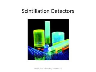
Scintillation Counters and Photomultiplier Tubes 2. Light generation in scintillators • Different scintillator materials • Plastic scintillator -- good for large areas • Sodium Iodide (NaI) • BGO (Bi4Ge2O12) • Lead Tungstate (PbWO4) • Focus on plastic scintillator • Composition • Polystyrene or acrylic (plexiglass, CHCN) • Doped with small admixture of a fluor • Fluor is organic macro-molecule like • POPOP: 1,4-Bis-[2-(5-phenyloxazolyl)]-benzene • C24H16N2O2 • Light generated by fluorescence process • One of the energy loss mechanisms when charged • particles pass through matter • Similar to television screen or computer monitor • Quantum mechanical process • Light (photons) emitted isotropically • Emission spectrum from typical scintillator • Relation to visible light spectrum Inorganic crystals
Scintillation Counters and Photomultiplier Tubes 2. Light generation in scintillators • Different scintillator materials • Plastic scintillator -- good for large areas • Sodium Iodide (NaI) • BGO (Bi4Ge2O12) • Lead Tungstate (PbWO4) • Focus on plastic scintillator • Composition • Polystyrene or acrylic (plexiglass, CHCN) • Doped with small admixture of a fluor • Fluor is organic macro-molecule like • POPOP: 1,4-Bis-[2-(5-phenyloxazolyl)]-benzene • C24H16N2O2 • Light generated by fluorescence process • One of the energy loss mechanisms when charged • particles pass through matter • Similar to television screen or computer monitor • Quantum mechanical process • Light (photons) emitted isotropically • (That is, “in all directions” along the particle’s path • in the scintillator material) • Emission spectrum from typical scintillator • Relation to visible light spectrum Inorganic crystals
Scintillation Counters and Photomultiplier Tubes Television Cathode Ray Tube
Energy absorption and emission diagram Electrons excited to higher energy levels when a charged particle passes, absorbing part of its energy Electron ground state Electrons drop back to ground state, emitting fluorescence or scintillation light
Scintillation Counters and Photomultiplier Tubes Typical plastic scintillator emission spectrum Wavelength of emitted light • 1 nm = 1 nanometer = 1 10-9 meter • For reference, 1 nm = 10 Angstroms, • where 1 Angstrom is approximate size of an atom • Maximum emission at about 425 nm
Scintillation Counters and Photomultiplier Tubes Review of (commonly used) prefixes • 1012 tera (trillion) • 109 giga (billion, “10 Gigabyte hard drive”) • 106 mega (million, “128 Megabytes of RAM”) • 103 kilo (thousand, 1 kilogram = 2.2 pounds) • 10– 2 centi (hundredth, 1 in. = 2.54 cm) • 10– 3 milli (thousandth, “50 mV per division”) • 10– 6 micro (millionth) • 10– 9 nano (billionth, “nanosecond”) • 10– 12 pico (trillionth) • 10– 15 femto
Scintillation Counters and Photomultiplier Tubes The wavelengths of visible light 400 nm 700 nm Wavelength in nanometers (nm) 101 103 1011 nm = 100 m
Scintillation Counters and Photomultiplier Tubes Wavelength in nanometers (nm)
Scintillation Counters and Photomultiplier Tubes Electromagnetic waves (visible light, radio waves, etc.) are characterized by a wavelength (Greek lambda, ) and a frequency (Greek nu, ). They are related by the simple formula = c c = the speed of light in a vacuum = 186,000 miles/sec = 3 108 meters/second Examples: 1. Blue light = 425 nm = 425 10-9 m Blue light frequency = c / = 7 1014 cycles per second (1 cycle per second = 1 hertz, hz) 2. Omaha NPR radio station, “91.5 on your FM dial” “91.5” means a frequency of 91.5 Megahertz (Mhz) Wavelength of the radio waves is = c / = 3.3 meters
Scintillation Counters and Photomultiplier Tubes 3. Light Collection • Purpose -- Direct as much generated light as possible to • the photodetector • Need for making counters light tight • Light transmission within scintillator • Reflections from surfaces, total internal reflection • Transmission through surfaces • Critical angle • Importance of smooth polished surfaces • Use of reflective coverings • (foil, white paint, white paper, black paper) • Multiple bounces (many!) • Ray-tracing simulation programs • Attenuation of light in scintillator
Scintillation Counters and Photomultiplier Tubes Light transmission within scintillator Charged particle passes through here Scintillator Light rays Photomultiplier tubes
Scintillation Counters and Photomultiplier Tubes Reflection and transmission at surfaces Air Scintillator material Light totally internally reflected for incident angle greater than critical which depends on optical properties of scintillator and air Scintillator Air Refraction (i.e. transmission) outside scintillator for incident angle less than critical
Scintillation Counters and Photomultiplier Tubes 3. Light Collection • Different light collection schemes • Different types of plastic light guides • Air light guides (KASCADE) • CASA scheme • Not optimal, PMT glued onto surface • Wavelength-shifting side bars • Embedded wavelength-shifting optical fibers • Connected to clear optical fibers • Can transport light over long distance • Other fiber optics applications • Laproscopic surgery • Telecommunications
Light collection in the KASCADE experiment Electron and photon detector Photomultiplier 33 kg of liquid scintillator Argon-filled space (better light transmission than air) Light emitted from scintillator is guided by conical reflecting surfaces to photomultiplier tube above
Light collection in the KASCADE experiment Muon detector Wavelength-shifting bars around perimeter of planes guide light to photomultiplier tubes 4 plastic scintillator planes
The CROP team at the Chicago Air Shower Array (CASA) site, September 30, 1999 U.S. Army Photo
Scintillation Counters and Photomultiplier Tubes Laproscopic surgery • Optical fibers transmit image to surgeon • Less intrusive technique
Scintillation Counters and Photomultiplier Tubes Optical Fibers • Fiber core and cladding optimized to • prevent leakage of light out of the fiber • 95% transmission over 1 km • If this were true for ocean water, you could • clearly see ocean bottom Transmission modes within optical fibers
Scintillation Counters and Photomultiplier Tubes What’s wrong with this picture?
Scintillation Counters and Photomultiplier Tubes Several scintillators tied together optically with optical fibers To photo-detector Wavelength-shifting optical fiber Scintillator planes
Scintillation Counters and Photomultiplier Tubes • Advantages and limitations of each type of light • read-out scheme • Definition of efficiency of light collection • Number of photons arriving at the photo-detector • Number of photons generated by charged particle • About 10% for light guide attached to side • A few percent for CASA counters
More PMTs Scintillator Scintillation Counters and Photomultiplier Tubes Discuss possible alternate light read-out schemes for CASA/CROP detectors PMT Reflective cone “Air” light guide Light Scintillator Charged particle Advantages and disadvantages?
Scintillation Counters and Photomultiplier Tubes Discuss possible alternate light read-out schemes for CASA/CROP detectors One or more PMTs Scintillator One or more clear plastic light guides attached to the sides Advantages and disadvantages?
Scintillation Counters and Photomultiplier Tubes Discuss possible alternate light read-out schemes for CASA/CROP detectors PMT Scintillator Wavelength-shifting sidebar Advantages and disadvantages?
Scintillation Counters and Photomultiplier Tubes Discuss possible alternate light read-out schemes for CASA/CROP detectors Splice to clear optical fibers Remote PMT Scintillator Wavelength-shifting fibers embedded in groves in scintillator Scintillator End view Advantages and disadvantages?
Typically, the pulse height as a function of distance x away from the near end of • the scintillator is described by the function • The distance L is called the “attenuation length” of this detector. L is the distance • a particle needs to be away from the PMT end of the scintillator to yield a pulse • height which is 1/e = 1/2.718 = 37% of the pulse height for a particle passing through • at x = 0. • A typical attentuation length for the scintillator above is L = 1.0 meter. • The attenuation length is a combination of two ingredients: • The absorption of light in the scintillator material itself as light propagates • toward the PMT • 2. The geometric effect of light traveling to the PMT from where it is generated Scintillation Counters and Photomultiplier Tubes Attenuation Length Observation: the light collection efficiency may depend on the place where the particle passes through the scintillator Particle passing near to PMT Particle passing far from PMT PMT Distance x Scintillator Light guide “Pulse height” far “Pulse height” near Pulse heights measured in millivolts (mV) on oscilloscope
Scintillation Counters and Photomultiplier Tubes Attenuation Length in CROP Detectors Expect largest signal pulse height for particle passing close to PMT. PMT Scintillator Expect smaller signal pulse height for particle passing through corner. The signal attenuation is approximately 50% for corner particles compared to particles passing near the PMT.
Scintillation Counters and Photomultiplier Tubes 4. Optical Interfaces and Connections • Purpose -- transmit light with high efficiency, • sometimes provide mechanical stability of detector • as well (should decouple the two tasks if possible) • Interface between scintillator material and • Light guide • Optical fiber • Wavelength-shifting bar • Interface between light guide or fiber and • photodetector • Commonly used • Optical cements and epoxies • Optical grease • Air gap
Scintillation Counters and Photomultiplier Tubes 5. Photodetectors and Photomultiplier Tubes • Purpose -- transform light into electric signal for • further processing of particle information • Examples • Photomultiplier tube (CROP focus) • Photodiode • Charged-coupled device • Avalanche photodiode (APD) • Visible Light Photon Counter (cryogenics) • Photomultiplier tube details • Entrance window • Must be transparent for light wavelengths which • need to enter tube • Common: glass • Fused silicate -- transmits ultraviolet as well
Scintillation Counters and Photomultiplier Tubes Schematic drawing of a photomultiplier tube (from scintillator) Photocathode Photons eject electrons via photoelectric effect Each incident electron ejects about 4 new electrons at each dynode stage Vacuum inside tube An applied voltage difference between dynodes makes electrons accelerate from stage to stage “Multiplied” signal comes out here
Scintillation Counters and Photomultiplier Tubes • Definition of Photomultiplier Tube Gain • = average number of electrons generated at each dynode • stage • Typically, = 4 , but this depends on dynode material • and the voltage difference between dynodes • n = number of multiplication stages • Photomultiplier tube gain = n • For n = 10 stages and = 4 , gain = 410 = 1 107 • This means that one electron emitted from the • photocathode (these are called “photoelectrons”) • yields 1 107 electrons at the signal output
Scintillation Counters and Photomultiplier Tubes Different types of dynode chain geometries Incoming light
Scintillation Counters and Photomultiplier Tubes The Photocathode • Incoming photons expel electrons from the metallic • surface of the photocathode via the photoelectric effect. • The effect was discovered by • Heinrich Hertz in 1887 and • explained by Albert Einstein • in 1905. • According to Einstein's theory, • light is composed of discrete • particles of energy, or quanta, • called PHOTONS. When photons with enough energy • strike the photocathode, they liberate electrons that have • a kinetic energy equal to the energy of the photons less • the “work function” (the energy required to free the • electrons from a particular material). • Einstein received the Nobel Prize for his 1905 paper • explaining the photoelectric effect. What were the other • two famous Einstein papers from 1905?
Scintillation Counters and Photomultiplier Tubes The Photocathode • Incoming photons expel electrons from the metallic • surface of the photocathode via the photoelectric effect. • The effect was discovered by • Heinrich Hertz in 1887 and • explained by Albert Einstein • in 1905. • According to Einstein's theory, • light is composed of discrete • particles of energy, or quanta, • called PHOTONS. When photons with enough energy • strike the photocathode, they liberate electrons that have • a kinetic energy equal to the energy of the photons less • the “work function” (the energy required to free the • electrons from a particular material). • Einstein received the Nobel Prize for his 1905 paper • explaining the photoelectric effect. What were the other • two famous Einstein papers from 1905? • Theory of special relativity • Explanation of Brownian motion
Scintillation Counters and Photomultiplier Tubes The Photocathode • Photocathode composition • Semiconductor material made of antimony (Sb) and • one or more alkalai metals (Cs, Na, K) • Thin, so ejected electrons can escape • Definition of photocathode quantum efficiency, h(l) • Number of photoelectrons released • h(l) = • Number of incident photons (l) on cathode • Typical photocathode quantum efficiency is 10 - 30% • Photocathode response spectrum • Need for matching scintillator light output spectrum with • photocathode response spectrum