CENTRIFUGAL PUMPS
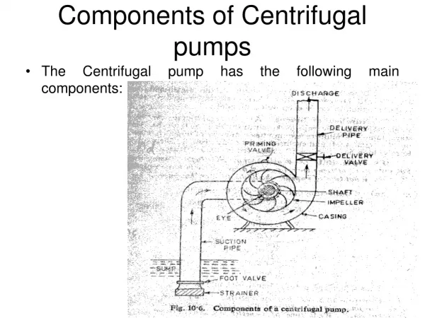
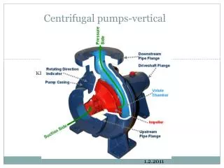
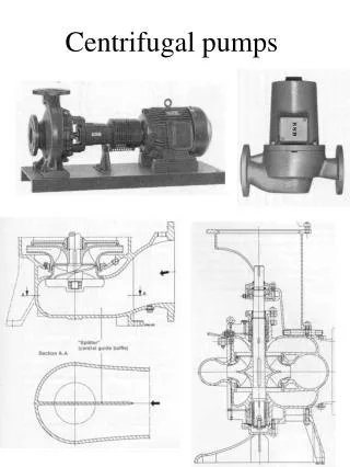
CENTRIFUGAL PUMPS. ROTATING COMPONENT & STATIONARY COMPONENT. General components of a Centrifugal Pump. Suction and Discharge Nozzle . Cut-away of a pump showing volute casing. Solid Casing . Seal Chamber and Stuffing Box . Seal Chamber and Stuffing Box. o Gland:


CENTRIFUGAL PUMPS
E N D
Presentation Transcript
Seal Chamber and Stuffing Box o Gland: is is a very important part of the seal chamber that gives the mechanical seal the desired fit on the shaft sleeve. The gland comprises of the seal flush, quench, cooling, drain, and vent connection ports as per the standard codes like API 682. o Throat Bushing: h a stationary device that forms a restrictive close clearance around the sleeve (or shaft) between the seal and the impeller. o Throttle bushing refers toa device that forms a restrictive close clearance around the sleeve (or shaft) at the outboard end of a mechanical seal gland. o Internal circulating device rerefers to device located in the seal chamber to circulate seal chamber fluid through a cooler or barrier/buffer fluid reservoir. Usually it is referred to as a pumping ring. o Mechanical Seal: The features of a mechanical seal will be discussed in Part-II of the article.
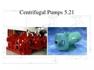
POMPA SENTRIFUGAL Produce a head and a flow by increasing the velocity of the liquid through the machine with the help of a impeller. • End suction pump • In-line pump • Double suction pump • Vertical multistage pump • Horizontal multistage pump • Submersible pumps • Self-priming pumps • Axial-flow pumps • Regenerative pumps
Working Mechanism of a Centrifugal Pump The impeller converts driver energy into the kinetic energy. The volute or diffuser is converts the kinetic energy into pressure energy A pump does not create pressure, it only provides flow. Pressure is a just an indication of the amount of resistance to flow.
CAVITATION running at less than 10% of its best efficiency point
PENYEBAB CAVITATION • pump installed above liquid level • pump drawing from vacuum tank • high vapor pressure liquid • unusually long suction line • plant is at high altitude
Suction Cavitation Suction Cavitation occurs when --- NPSHA < NPSHR Symptoms 1. The pump sounds like it is pumping rocks! 2. High Vacuum reading on suction line 3. Low discharge pressure/High flow Causes 1. Clogged suction pipe 2. Suction line too long 3. Suction line diameter too small 4. Suction lift too high 5. Valve on Suction Line only partially open Remedies 1. Remove debris from suction line 2. Move pump closer to source tank/sump 3. Increase suction line diameter 4. Decrease suction lift requirement 5. Install larger pump running slower which will decrease the NPSHR pump 6. Increase discharge pressure 7. Fully open Suction line valve
Discharge Cavitation occurs when the pump discharge head is too high Symptoms 1. The pump sounds like it is pumping rocks! 2. High Discharge Gauge reading 3. Low flow Causes 1. Clogged discharge pipe 2. Discharge line too long 3. Discharge line diameter too small 4. Discharge static head too high 5. Discharge line valve only partially open Remedies 1. Remove debris from discharge line 2. Decrease discharge line length 3. Increase discharge line diameter 4. Decrease discharge static head requirement 5. Install larger pump which will maintain the required flow without discharge cavitating 6. Fully open discharge line valve
PRINSIP KERJA CENTIFUGAL PUMP(Aplikasi Bernouli) 3 increases liquid pressure by increasing fluid velocity by action of a rotating impeller 2 1 1 1 2 Impeler menaikan energi Kinetik 2 3 Difuser E kin menjadi Tekanan Pump will pump all fluids to the same height if the shaft is turning at the same rpm.
Centrifugal Pumps • "constant head machines“ and not a constant pressure machine, since pressure is a function of head and density. The higher ρ, the more power is required to get the shaft to the same rpm
DEFINITION OF IMPORTANT TERMS The key performance parameters of centrifugal pumps are Head, Capacity, BHP (Brake horse power), Pump curves BEP (Best efficiency point) and Specific speed.
Capacity The capacity depends on a number of factors like: Impeller size Impeller rotational speed RPM Size and shape of cavities between the vanes Size of the pump and its inlet and outlet sections Pump suction and discharge temperature and pressure conditions Process liquid characteristics i.e. density, viscosity
AFFINITY LAWS FOR ROTATING EQUIPMENT Capacity proportional to impeller speed and/or impeller diameter. Head proportional to the square of speed and diameter Power proportional to the cube of speed and diameter (as does NPSH)
BHP & FHP Brake Horse Power Fluid Horse Power Energi/massa Energi diterima fluida Energi dari poros pompa : laju alir massa P :Efisiensi Pompa M :Efisiensi Motor Energi dari motor penggerak
Pump Performance Curve Correlation of pump capasity to its HEAD The pump performance curve also shows its efficiency (BEP), required input power (in BHP), NPSHr, and other information such as pump size and type, impeller size, rpm etc. This curve is plotted for a constant speed (rpm) and a given impeller diameter (or series of diameters). Pump curves are based on a specific gravity of 1.0. Other specific gravities must be considered by the user.
KURVA KARAKTERISTIK POMPA (D impeler dan rpm tetap) hanya pada flow rendah
PUMP PERFORMANCE CURVE Pump Design ImpellerDiameter Pump Speed Total Dynamic Head Efficiency BHP Required ? NPSH Required BHP = QHρg NPSH required is a function of the pump design Flow
Best Efficiency Point (BEP) The H, NPSHr, efficiency, and BHP all vary with flow rate, Q. Best Efficiency Point (BEP) is the capacity at maximum impeller diameter at which the efficiency is highest. All points to the right or left of BEP have a lower efficiency
PERFORMANCE COMPARISON OF CENTRIFUGAL PUMP SPECIFIC SPEED Q= Kapasitas pada BEP Suction specific speed
SPECIFIC SPEED Adalah indeks disain pompa, yang menunjukkan kesamaan GEOMETRI POMPA, digunakan untuk klasifikasi IMPELER pompa sesuai jenis dan bentuknya (proportions). Pompa yang ukurannya berbeda namun memiliki Ns sama , dianggap secara sama GEOMETRI nya.
Specific Speed and Pump Type Specific Speed, Ns Radial impellers are generally low flow high head designs whereas axial flow impellers are high flow low head designs.
SPECIFIC SPEED Specific speed identifies the approximate acceptable ratio of the impeller eye diameter (D1) to the impeller maximum diameter (D2) in designing a good impeller. Ns: 500 to 5000; D1/D2 > 1.5 - radial flow pumpNs: 5000 to 10000; D1/D2 < 1.5 - mixed flow pumpNs: 10000 to 15000; D1/D2 = 1 - axial flow pump
REQUIREMENTS FOR CONSISTENT OPERATION No cavitation of the pump occurs throughout the broad operating range a certain minimum continuous flow is always maintained during operation.
MINIMUM FLOW IN CENTRIFUGAL PUMPS Small pumps 30% of the flow at BEP (best efficiency point). Larger and multistage pumps 50% of BEP flow. Reduced flow causes : Cases of heavy leakages from the casing, seal, and stuffing boX Deflection and shearing of shafts Seizure of pump internalsClose tolerances erosion Separation cavitation Product quality degradation Excessive hydraulic thrust Premature bearing failures
SOAL SOAL POMPA 9.1. Berapa galon per menit yang dapat ditransfer oleh pompa piston yang memiliki luas area 10in2 dan panjang stroke 5 in dengan speed 1 Hz. A=1in2 Speed=1Hz 5in 1Hz- 1detik dalam 1 siklus 1menit= 60 siklus Q=A.L.N Q=1X5X60 in2 per menit
P2 P1 SOAL SOAL POMPA 9.2 Hitung hydraulic horse power untuk memompa 500 galon per menit dari inlet 5 psig ke outlet 30 psig Q=500 galon/min P1=5 psi P2=30 psi
P2 P1 SOAL SOAL POMPA 9.4. Suatu pompa mentransfer 50galon per menit fluida dari tekanan 30psi ke 100 psi. Power yang disuplai ke motor adalah 2.8 hp Jika perubahan elevasi dan kecepatan diabaikan hitung efiensi motor. Hitung kenaikan suhu air jika proses dianggap adiabatik Q=50 galon/min P1=5 psi P2=30 psi Po=2,8hp
Soal soal Pompa 9.5. Fluida mercury ingin dipompakan dengan menggunakan PD pump.Diasumsikan tidak ada friksi dan tekanan uap mercury diabaikan. Hitung suction lift.
Soal soal Pompa 9.6 Suatu pompa sentrifugal dioperasikan pada 1800 rpm. Jika fluidanya air, hitung perbedaan tekanan yang dapat dibangkitkan oleh pompa untuk impeler 1,3, 10 in.Hitung jika rpm 3600
Soal soal Pompa 9.6 Dari data flow rate dan dan head suatu kurva performa pompa hitung efiensi. Misalkan untuk Flow=5ft3/s headnya 330ft. Power=225hp.
Soal soal Pompa 9.5. Suatu pompa sentrifugal digunakan untuk memompa mercury. Tekanan inlet 200psi. Diameter impeler 2in. Pompa diputar dengan kecepatan 20.000 rpm. Estimasikan tekanan outlet
Soal soal Pompa 9.9 Suatu pompa diuji untuk fluida air pada rpm 1800 kapasitasnya 200gal per min kenaikan tekanan 50 psi. Efiensi 75 %. Kita ingin menggunakan pompa ini untuk memompa merkusri pada rpm dan flowrate yang sama. Perkirakan kenaikan tekanan, hp dan jika efisiensi sama. rpm=1800 Q= 200gal per min P= 50 psi. = 75 %. rpm=1800 Q= 200gal per min P =? psi. = 75 %.